KS0361 KS0365 Micro:bit 37 sensors starter Kit
IMPORTANT NOTE:
The 37 sensors starter kit (SKU KS0361) Not Includes micro:bit v2 board.
The 37 sensors starter kit (SKU KS0365) Includes a micro:bit v2 board.
1.Introduction
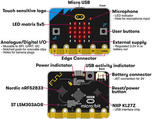
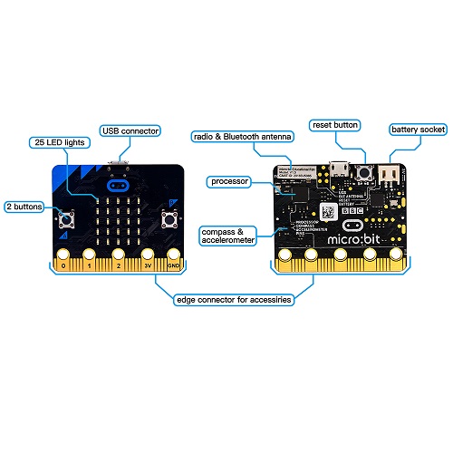
(1) What is Micro:bit?
Designed by BBC, micro:bit main board aims to help children aged above 10 years old to have a better learning of programming.
It is equipped with loads of components, including a 5*5 LED dot matrix, 2 programmable buttons, a compass, and a BT module.
This new version, that’s the micro:bit 2.0 board, has a touch-sensitive logo and a MEMS microphone. And there is a built-in buzzer which can play sounds. The golden fingers and gears added provide a better fixing of crocodile clips.
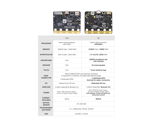
Moreover, this board has a sleeping mode to lower the power consumption of battery and it can be entered if users long press the Reset & Power button on the back of it. More importantly, the CPU capacity of this version is much better than that of the V1.5 and the V2 has more RMA.
In final analysis, the V2 Micro:bit main board can allow customers to explore more functions so as to make more innovative products.
Serving as a better device for learning some basic knowledge about microcontroller and electronics, this sensor kit is designed by Keyestudio to help programming enthusiasts enter this wonderful world.
In application, we can plug a shield in with DC7-9V to power not only the Micro bit board but also the sensors,modules.
And the shield can be connected by jumper cap to control the voltage of ports V1 and V2 used to supply power for sensors. We plan to provide instructions for using this board and sensors/ modules, including offering connection diagrams and test code.
Comparison between V2.0 & V1.5
Micro:bit main board V2.0
Micro:bit main board V1.5
More details:
For Micro: Bit main board V2, pressing the Reset & Power button , it will reset the Micro: Bit and rerun the program. If you hold it tight, the red LED will slowly get darker.When the power indicator flickers into darkness, releasing the button and your Micro: Bit board will enter sleep mode for power saving .This will make the battery more durable. And you could press this button again to “wake up” your Micro:bit.
For more information,please resort to following links:
https://tech.microbit.org/hardware/
https://microbit.org/new-microbit/
https://www.microbit.org/get-started/user-guide/overview/
https://microbit.org/get-started/user-guide/features-in-depth/
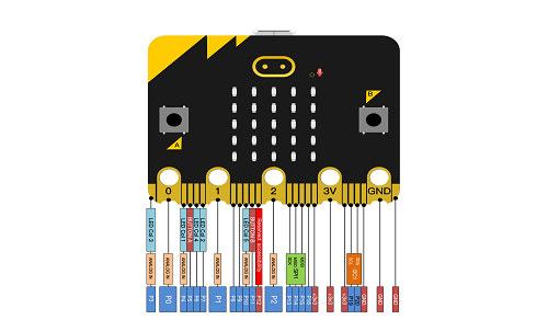
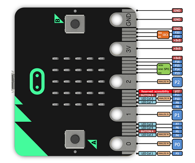
(3) Pinout
Micro:bit main board V2.0 VS V1.5
Browse the official website for more details:
https://tech.microbit.org/hardware/edgeconnector/
https://microbit.org/guide/hardware/pins/
(4) Notes for the application of Micro:bit main board V2.0
a. It is recommended to cover it with a silicone protector to prevent short circuit for it has a lot of sophisticated electronic components.
b. Its IO port is very weak in driving since it can merely handle current less than 300mA. Therefore, do not connect it with devices operating in large current,such as servo MG995 and DC motor or it will get burnt. Furthermore, you must figure out the current requirements of the devices before you use them and it is generally recommended to use the board together with a Micro:bit shield.
c. It is recommended to power the main board via the USB interface or via the battery of 3V. The IO port of this board is 3V, so it does not support sensors of 5V. If you need to connect sensors of 5 V, a Micro: bit expansion board is required.
d. When using pins(P3、P4、P6、P7、P10)shared with the LED dot matrix, blocking them from the matrix or the LEDs may display randomly and data about sensors maybe wrong.
e. The battery port of 3V cannot be connected with battery more than 3.3V or the main board will be damaged.
f. Forbid to use it on metal products to avoid short circuit.
To put it simple, Micro:bit V2 main board is like a microcomputer which has made programming at our fingertips and enhanced digital innovation. And about programming environment, BBC provides a website: https://microbit.org/code/, which has a graphical MakeCode program easy for use.
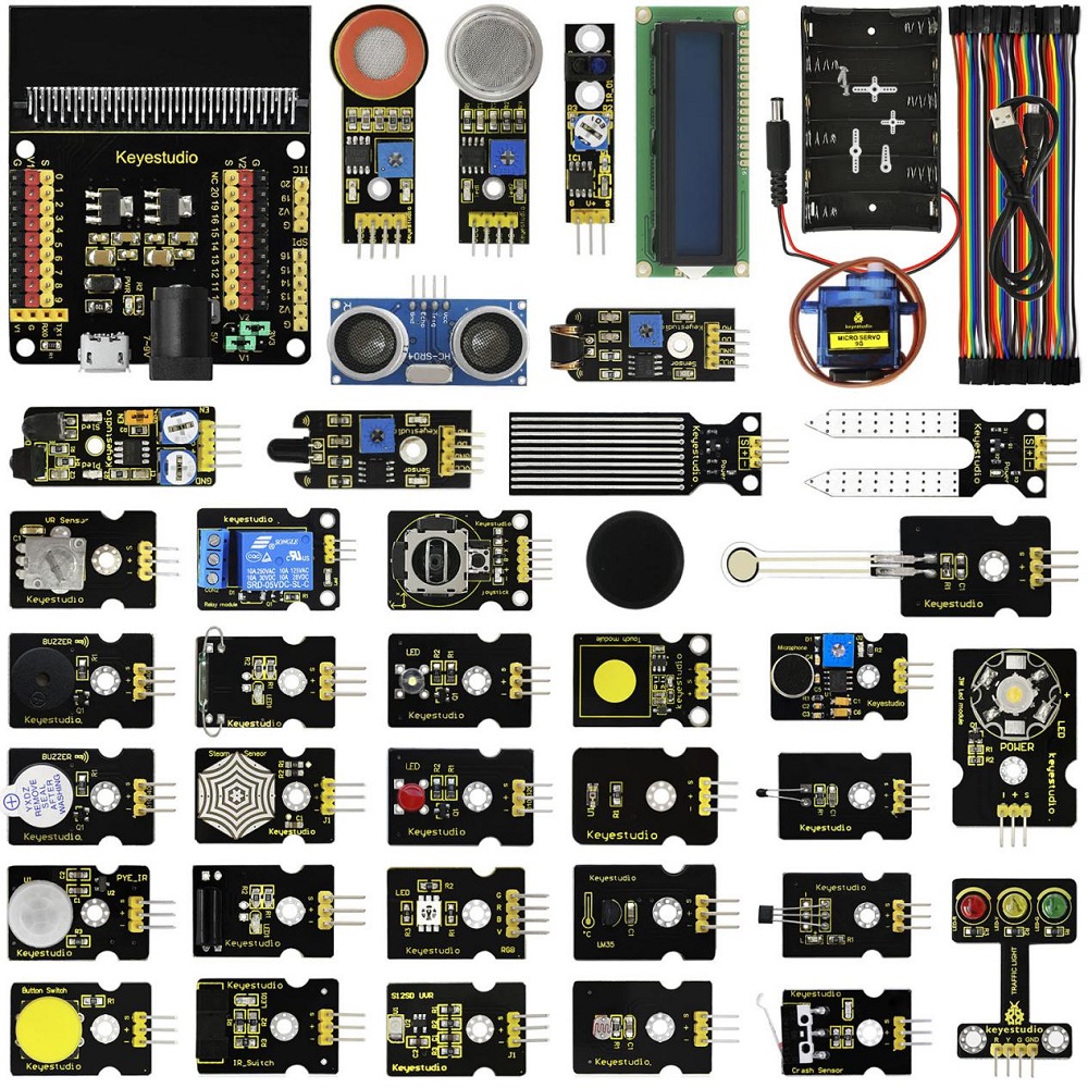
2.Kit List
No. |
Components |
Quantity |
Picture |
|---|---|---|---|
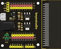
1 |
Keyestudio Micro: bit Sensor Shield V2 |
1 |
|
2 |
Keyestudio White LED Module |
1 |
|
3 |
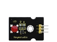
Keyestudio Red LED Module |
1 |
|
4 |
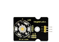
Keyestudio 3W LED Module |
1 |
|
5 |
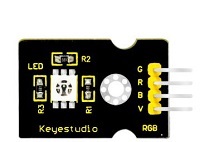
Keyestudio RGB LED Module |
1 |
|
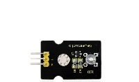
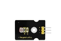
6 |
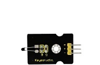
Keyestudio Analog Temperature Sensor |
1 |
|
7 |
Keyestudio Photocell Sensor |
1 |
|
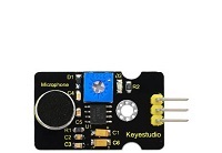
8 |
Keyestudio Analog Sound Sensor |
1 |
|
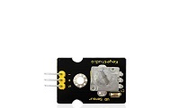
9 |
Keyestudio Potentiometer Sensor |
1 |
|
10 |
Keyestudio Passive Buzzer Module |
1 |
|
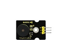
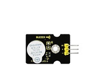
11 |
Keyestudio Active Buzzer Module |
1 |
|
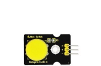
12 |
Keyestudio Digital Push Button |
1 |
|
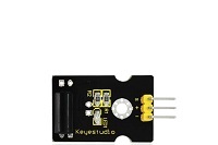
13 |
Keyestudio Digital Tilt Sensor |
1 |
|
14 |
Keyestudio Photo Interrupter Module |
1 |
|
15 |
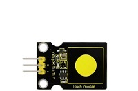
Keyestudio Capacitive Touch Sensor |
1 |
|
16 |
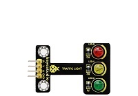
Keyestudio Traffic Light Module |
1 |
|
17 |
Keyestudio Hall Magnetic Sensor |
1 |
|
18 |
Keyestudio Line Tracking Sensor |
1 |
|
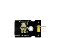
19 |
Keyestudio Infrared Obstacle Detector Sensor |
1 |
|
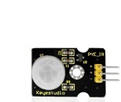
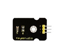
20 |
Keyestudio PIR Motion Sensor |
1 |
|
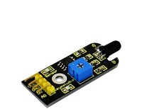
21 |
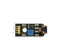
Keyestudio Flame Sensor |
1 |
|
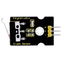
22 |
Keyestudio Crash Sensor |
1 |
|
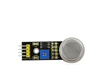
23 |
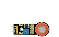
Keyestudio Analog Gas Sensor |
1 |
|
24 |
Keyestudio Analog Alcohol Sensor |
1 |
|
25 |
Keyestudio Reed Switch Module |
1 |
|
26 |
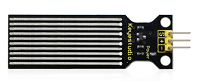
Keyestudio Water Sensor |
1 |
|
27 |
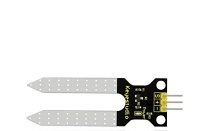
Keyestudio Soil Humidity Sensor |
1 |
|
28 |
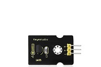
Keyestudio LM35 Linear Temperature Sensor |
1 |
|
29 |
Keyestudio Vibration Sensor |
1 |
|
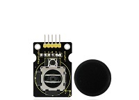
30 |
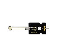
Keyestudio Thin-film Pressure Sensor |
1 |
|
31 |
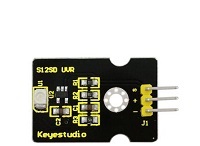
Keyestudio GUVA-S12SD 3528 Ultraviolet Sensor |
1 |
|
32 |
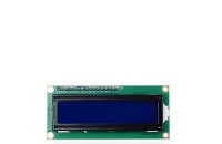
Keyestudio 1602 I2C Module |
1 |
|
33 |
Keyestudio TEMT6000 Ambient Light Sensor |
1 |
|
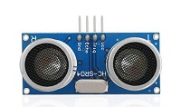
34 |
HC-SR04 Ultrasonic Module |
1 |
|
35 |
Keyestudio Joystick Module |
1 |
|
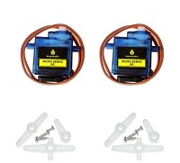
36 |
Keyestudio Micro:bit Servo |
1 |
|
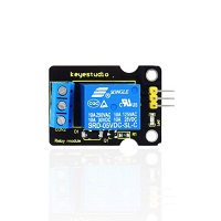
37 |
Keyestudio Single Relay Module |
1 |
|
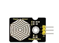
38 |
Keyestudio Steam Sensor |
1 |
|
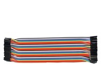
39 |
40pin F-F DuPont Jumper Wire |
1 |
|
40 |
USB Cable |
1 |
|
41 |
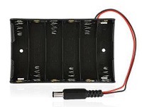
6 AA Battery Holder |
1 |
|


3.Install Micro:bit driver
If you have downloaded micro:bit driver, then no need to download it again.
If it is you first time to use micro:bit main board, then you will have to download the driver.
First of all, connect the micro:bit to your computer using a USB cable.
And enter website https://www.dropbox.com/sh/w5mv8mvvufti0uj/AADTFPTV8NBN0IxQj_3TZ8ETa?dl=0 to download the driver file of micro:bit  .
.
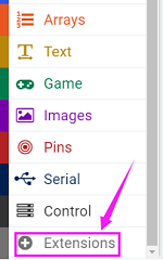
4.Instructions
The following instructions are applied for Windows system but can also serve as a reference if you are using a different system.
4.1 Write code and program
This chapter describes how to write program with the Micro: bit main board V2 and load the program to the board.
You are recommended to browse the official website of Micro:bit for more details, and the link is attached below:
https://microbit.org/guide/quick/
Step 1: connect the Micro: bit main board V2 with your computer
Firstly, link the Micro: bit main board V2 with your computer via the USB cable. Macs, PCs, Chromebooks and Linux(including Raspberry Pi)systems are all compatible with this board.
Note that if you are about to pair the board with your phone or tablet, please refer to this link:
https://microbit.org/get-started/user-guide/mobile/
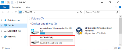
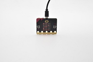
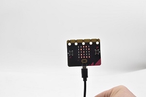
Secondly, the red LED on the back of the board is on, which means the board is powered. Then Micro: bit main board V2 will appear on your computer as a driver named “MICROBIT(E:)”. Please note that it is not an ordinary USB disk as shown below.
Step 2: write programs
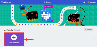
View the link https://makecode.microbit.org/ in your browser;
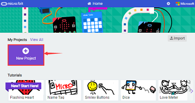
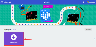
Click ‘New Project’;
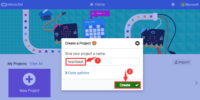
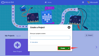
The dialog box‘Create a Project’ appears, fill it with ‘heartbeat’ and click‘Create √’to edit.
(If you are running Windows 10 system, it is also viable to edit on the APP MakeCode for micro:bit , which is exactly like editing in the website. And the link to the APP is https://www.microsoft.com/zh-cn/p/makecode-for-micro-bit/9pjc7sv48lcx?ocid=badgep&rtc=1&activetab=pivot:overviewtab
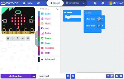
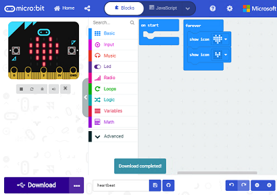
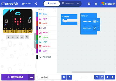
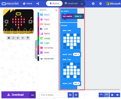
Write a set of micro:bit code. You can drag some modules in the Blocks to the editing area and then run your program in Simulator of MakeCode editor as shown in the picture below, which demonstrates how to edit ‘heartbeat’ program .
As for loading test code , please turn to Chapter 4.5. And introduction of MakeCode is on the next chapter 4.2.
Step 3: download test code
If your computer is Windows 10 and you have downloaded the APP MakeCode for micro:bit to write program, what you will have to do to download the program to your Micro: bit main board V2 is merely clicking the ‘Download’ button, then all is done.
If you are writing program through the website, following these steps:
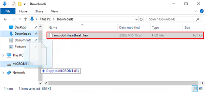
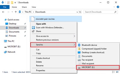
Click the ‘Download’ in the editor to download a “hex” file, which is a compact program format that the Micro: bit main board can read. Once the hexadecimal file is downloaded, copy it to your board V2 just like the process that you copy the file to the USB driver. If you are running Windows system, you can also right-click and select ‘Send to → MICROBIT (E:) ‘to copy the hex file to the Micro: bit main board V2

You can also directly drag the “hex” file onto the MICROBIT (E:) disk.
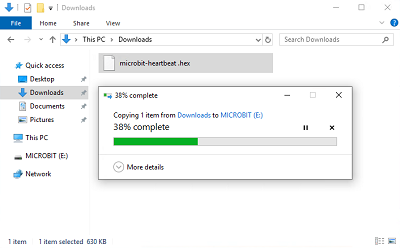
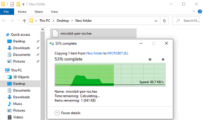
During the process of copying the downloaded hex file to the Micro: bit main board V2, the yellow signal light on the back side of the board flashes. When the copy is completed, the yellow signal light will stop flashing and remain on.
Step 4: run the program
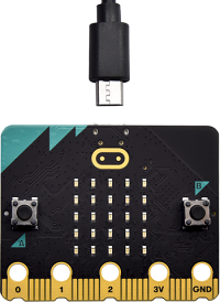
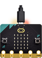
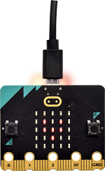
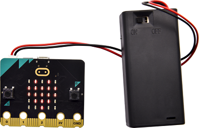
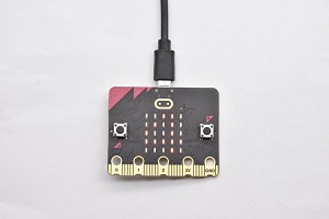
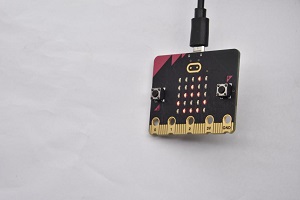
After the program is uploaded to the Micro: bit main board V2, you could still power it via the USB cable or change to via an external power. The 5 x 5 LED dot matrix on the board displays the heartbeat pattern.
|
|
|---|---|
Power via USB cable |
Power via external power (3V) |
Step 5:other programming languages
This chapter has described how to use the Micro: bit main board V2.
But except for the MakeCode graphical programming introduced you can also write Micro: bit programs in other languages. Go to the link: https://microbit.org/code/ to know about other programming languages , or view the link: https://microbit.org/projects/, to find something you want to have a go.
4.2 Makecode:
Browse https://makecode.microbit.org/ and enter MakeCode online editor or open the APP MakeCode for micro:bit of Windows 10.
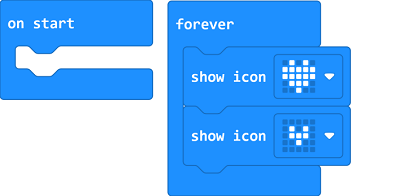
Click“New Project”, and input“heartbeat”,then enter MakeCode editor, as shown below:
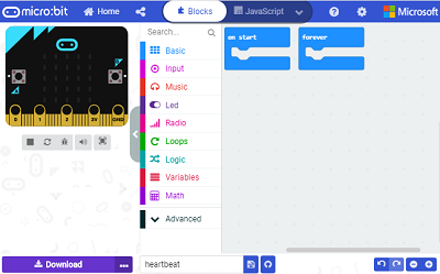
There are blocks“on start”and“forever”in the code editing area.
When the power is plugged or reset,“on start”means that the code in the block only executes once, while“forever”implies that the code runs cyclically.
4.3.Quick Download:
As mentioned before, if your computer is Windows 10 and you have downloaded the APP MakeCode for micro:bit to write programs, the program written can be quickly downloaded to the Micro: Bit main board V2 by selecting ‘Download’.
While it is a little trickier if you are using a browser to enter makecode. However, if you use Google Chrome, suitable for Linux,macOS and Windows 10, the process can be quicker too.
We use the webUSB function of Chrome to allow the internet page to access the hardware device connected USB.
You could refer to the following steps to connect and pair devices.
Device pairing:
Connect micro:bit to your computer by USB cable;
Click“…”beside“Download”and click“Pair device”;
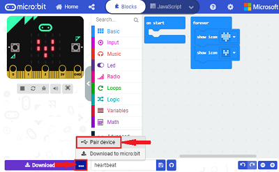
Then click another“Pair device”as shown below:
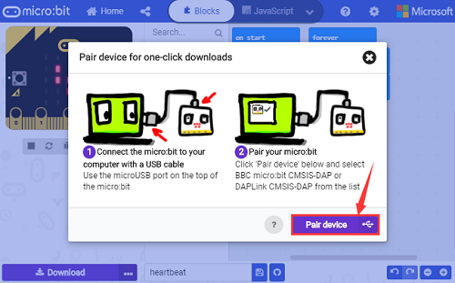
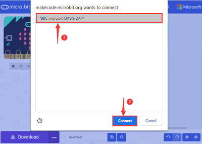
Then select“BBC micro:bit CMSIS-DPA” and click“Connect”. If “BBC micro:bit CMSIS-DPA”does not show up for selection, please refer to https://makecode.microbit.org/device/usb/webusb/troubleshoot
Update the firmware of the micro:bit V2: https://microbit.org/guide/firmware/
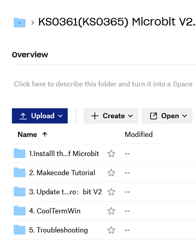
If the links are too troublesome for you , then you can also turn to our‘Troubleshooting Downloads with WebUSB’and“upload the firmware”in the folder we provided.
Then click“Download”. The program is directly downloaded to Micro: Bit main board V2 and the sentence“Download completed!” appears.
4.4 Resources and test code
We also provide a link https://fs.keyestudio.com/KS0361-0365 containing the information of the product from relevant tools to test codes, tutorials and troubleshooting methods as well, as shown in the figure below:
4.5 Input test code
We provide hexadecimal code files (project files) for each project. The file contains all the contents of the project and can be imported directly, or you can manually drag the code blocks to complete the program for each project. For simple projects, dragging a block of code to complete the program is recommended. For complex projects, it is recommended to conduct the program by importing the hexadecimal code file we provide.
Let’s take the “Heatbeat” project as an example to show how to load the code.
Open the Web version of Makecode or the Windows 10 App version of Makecode.
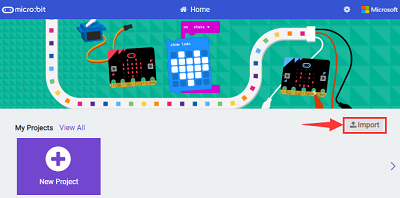
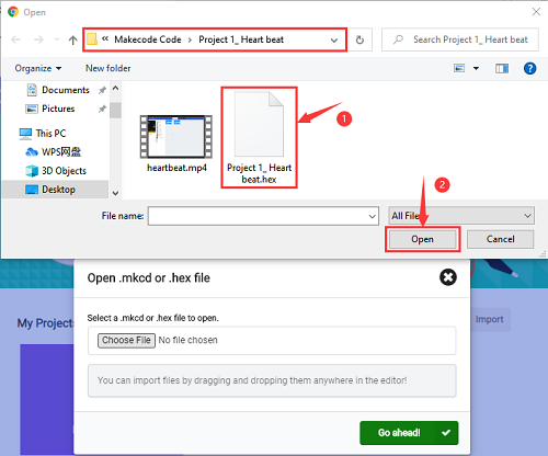
Click“Import File”
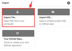
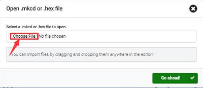
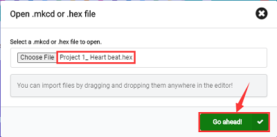
Select“ ../Makecode Code/Project 1_ Heart beat/Project 1_ Heart beat.hex” ; Then click “Go ahead”.
In addition to importing the test code file provided into the Makecode compiler above, you can also drag the the test code file provided into the code editing area of the Makecode compiler, as shown in the figure below:
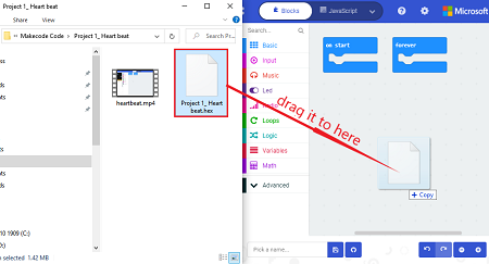
After a few seconds, it is done.
Note: if your computer system is Windows7 or 8 instead of Windows 10, the pairing cannot be done via Google Chrome. Therefore, digital signal or analog signal of sensors and modules cannot be shown on the serial port simulator. However, you need to read the corresponding digital signal or analog signal.So what can we do? You can use the CoolTerm software to read the serial port data of the microbit. Next chapter is about how to install CoolTerm.
**4.6 CoolTerm Installation **
CoolTerm program is used to read the data on serial port.
Download CoolTerm program:
https://freeware.the-meiers.org/
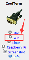
(1)After the download, we need to install CoolTerm program file, below is Windows system taken as an example.
(2)Choose“win”to download the zip file of CoolTerm
(3)Unzip file and open it. (also suitable for Mac and Linux system)
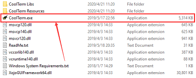
(4)Double-click 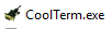 .
.
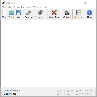
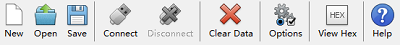
The functions of each button on the Toolbar are listed below: http://wiki.keyestudio.com/index.php/File:IDE.png
|
Open up a new Terminal |
|---|---|
|
Open a saved Connection |
|
Save the current Connection to disk |
|
Open the Serial Connection |
|
Close the Serial Connection |
|
Clear the Received Data |
|
Open the Connection Options Dialog |
|
Display the Terminal Data in Hexadecimal Format |
|
Display the Help Window |


5. Projects
Project 1: Heartbeat
1. Project Introduction
This project is easy to conduct with a micro:bit V2 main board, a Micro USB cable and a computer. The micro:bit LED dot matrix will display a relatively big heart-shaped pattern and then a smaller one. This alternative change of this pattern is like heart beating. This experiment serves as a starter for your entry to the programming world.
2. Components Needed:
Micro:bit main board V2 *1
USB cable*1
3. Connection Diagram:
Attach the Micro:bit main board V2 to your computer via the USB cable.
4. Test Code:
No need to worry though you are not good at programming. You will get help.
Firstly, you can view this link https://makecode.micro:bit.org/reference to find more information about micro: bit blocks. Then this link https://makecode.micro:bit.org/ can help you write code.
5. Test Results:
After uploading test code to micro:bit main board V2 and keeping the connection with the computer to power the main board, the LED dot matrix shows pattern “ ”and then “
 ”alternatively.
( Please refer to chapter 4.3 to know how to download test code quickly.)
If the downloading is not smooth, please remove the micro USB from the main board and then reconnect them and reopen Makecode to try again.
Project 2: Light A Single LED
1. Project Introduction:
In this project, we intend to control a certain LED of the micro:bit main board V2 to shine.
2. Components Needed:
Micro:bit main board V2 *1
USB cable*1
3. Connection Diagram:
Attach the Micro:bit main board V2 to your computer via the USB cable.
4. Introduction of components:
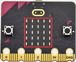
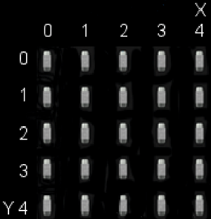
The LED dot matrix consists of 25 LEDs arranged in a 5 by 5 square. In order to locate these LEDs quickly, as the figure shown below, we can regarded this matrix as a coordinate system and create two aces by marking those in rows from 0 to 4 from top to bottom, and the ones in columns from 0 to 4 from the left to the right. Therefore, the LED sat in the second of the first line is (1,0)and the LED positioned in the fifth of the fourth column is (3,4)and others likewise.
5. Test Code:
6. Test Results
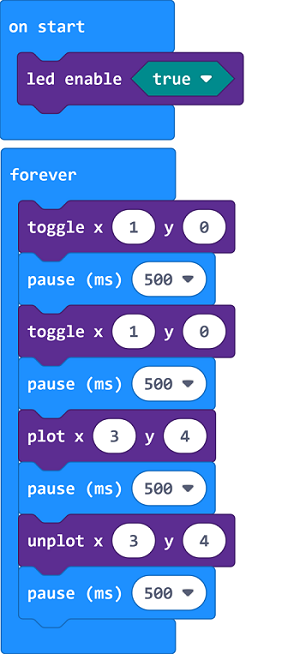
After uploading test code to micro:bit main board V2 and powering the main board via the USB cable, the LED in (1,0) lights up for 1s and the one in (3,4) shines for 1s and repeat this sequence.
Project 3: LED Dot Matrix
1. Project Introduction:
Dot matrices are very commonplace in daily life. They have found wide applications in LED advertisement screens, elevator floor display, bus stop announcement and so on.
The LED dot matrix of Micro: bit main board V2 contains 25 LEDs in a grid. Previously, we have succeeded in controlling a certain LED to light by integrating its position value into the test code. Supported by the same theory, we can turn on many LEDs at the same time to showcase patterns, digits and characters.
What’s more, we can also click”show icon“ to choose the pattern we like to display. Last but not the least, we can design patterns by ourselves.
2. Components Needed:
Micro:bit main board V2 *1
USB cable*1
3. Connection Diagram:
Attach the Micro:bit main board V2 to your computer via the USB cable.
4. Test Code:
5. Test Results:
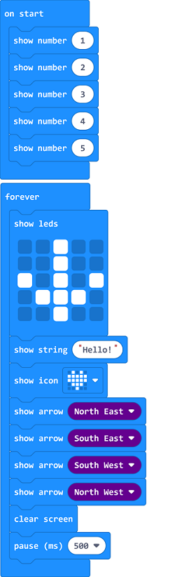
After uploading test code to micro:bit main board V2 and powering the main board via the USB cable, we find that the 5*5 dot matrix start to show numbers 1,2,3,4 and 5, and then it alternatively shows a downward arrow  , word “Hello”, a heart pattern
  , and an arrow pointing at northeast
  , then at southeast
  , then at southwest
  , and then at northwest
  .
.
Project 4: Programmable Buttons
1. Project Introduction:
Buttons can be used to control circuits. In an integrated circuit with a button, the circuit is connected when pressing the button and it is open the other way around.
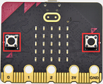
Micro: Bit main board V2 boasts three buttons, two are programmable buttons(marked with A and B), and the one on the other side is a reset button. By pressing the two programmable buttons three different signals can be input . We can press button A or B alone or press them together and the LED dot matrix shows A,B and AB respectively. Let’s get started.
2. Components Needed:
Micro:bit main board V2 *1
USB cable*1
3. Connection Diagram:
Attach the Micro:bit main board V2 to your computer via the USB cable.
4. Test Code 1:
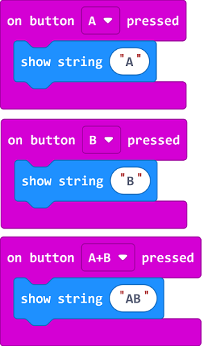
5. Test Results 1:
After uploading test code to micro:bit main board V2 and powering the main board via the USB cable, the 5*5 LED dot matrix shows A if button A is pressed, B if button B pressed, and AB if button A and B pressed together.
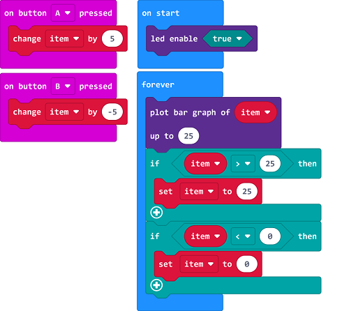
6. Test Code 2:
7. Test Results 2:
After uploading test code to micro:bit main board V2 and powering the main board via the USB cable, when pressing the button A the LEDs turning red increase while when pressing the button B the LEDs turning red reduce.
Project 5: Temperature Detection
1. Project Introduction:
In this project, we will make Micro: Bit main board V2 to detect temperature of external environment with the range of 40℃~105℃.
2. Components Needed:
Micro:bit main board V2*1
USB cable*1
3. Connection Diagram:
Attach the Micro:bit main board V2 to your computer via the Micro USB cable.
4. Test Code:
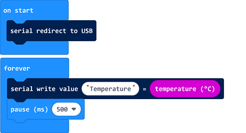
5. Test Results:
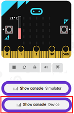
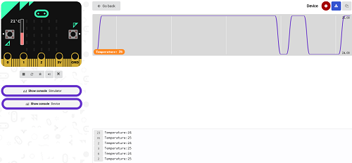
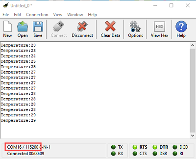
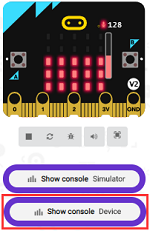
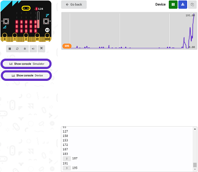
After uploading test code to micro:bit main board V2, powering the main board via the USB cable, and clicking “Show console Device”, the data of temperature shows in the serial monitor page as shown below:
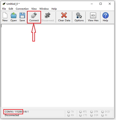
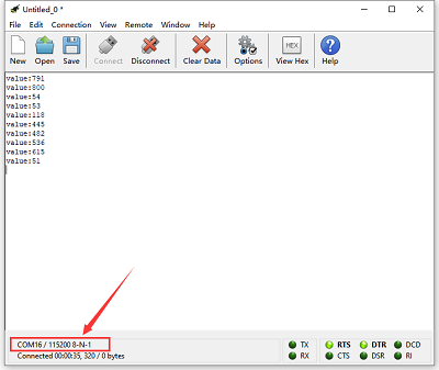
If you’re running Windows 7 or 8 instead of Windows 10, via Google Chrome won’t be able to match devices. You’ll need to use the CoolTerm serial monitor software to read data.
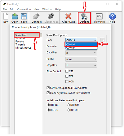
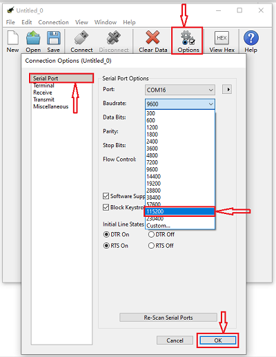
You could open CoolTerm software, click Options, select SerialPort, set COM port and baud rate to 115200 (after testing, the baud rate of USB SerialPort communication on Micro: Bit main board V2 is 115200), click OK, and Connect. The CoolTerm serial monitor shows the change of temperature in the current environment, as shown in the figures below :
Project 6: Geomagnetic Sensor
1. Project Introduction:
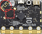
This project aims to explain the use of the Micro: bit geomagnetic sensor, which can not only detect the strength of the geomagnetic field, but also be used as a compass to find bearings. It is also an important part of the Attitude and Heading Reference System (AHRS). Micro: Bit main board V2 uses LSM303AGR geomagnetic sensor, and the dynamic range of magnetic field is ±50 gauss. In the board, the magnetometer module is used in both magnetic detection and compass.
In this experiment, the compass will be introduced first, and then the original data of the magnetometer will be checked. The main component of a common compass is a magnetic needle, which can be rotated by the geomagnetic field and point toward the geomagnetic North Pole (which is near the geographic South Pole) to determine direction.
2. Components Needed:
Micro:bit main board V2 *1
USB cable*1
3. Connection Diagram:
Attach the Micro:bit main board V2 to your computer via the USB cable.
4. Test Code 1:
5. Test Results:
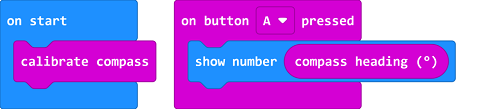
After uploading test code to micro:bit main board V2 and powering the board via the USB cable, and pressing the button A, the board asks us to calibrate compass and the LED dot matrix shows “TILT TO FILL SCREEN”. Then enter the calibration page. Rotate the board until all 25 red LEDs are on as shown below:
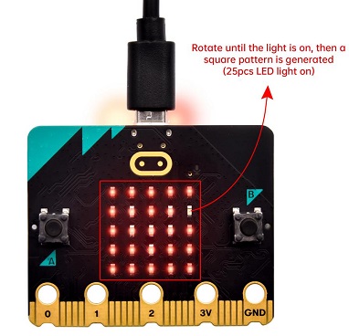
After that, a smile pattern  appears, which implies the calibration is done. When the calibration process is completed, pressing the button A will make the magnetometer reading display directly on the screen. And the direction north, east, south and west correspond to 0°, 90°, 180° and 270°.
6. Test Code 2:

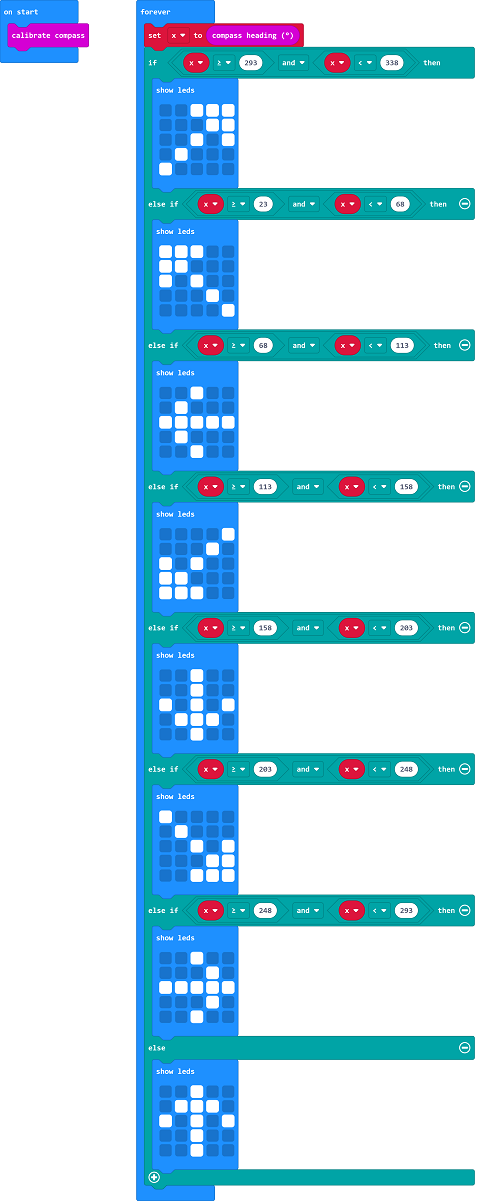
This module can keep reading data to determine direction, so does point to the current magnetic North Pole by arrow.
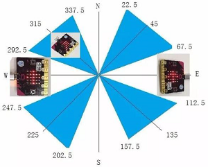
As shown in the figure, if the reading is between 292.5 and 337.5, the LED dot matrix displays an arrow pointing to the top right. Since 0.5 cannot be inputted in the code,the values added in the code are 293 and 338.Then add other logical criteria to form a compete test code as shown below:
7. Test Results 2:
Upload the test code to micro:bit main board V2, power the board via the USB cable, and finish the calibration process following the instructions.
Rotating the Micro: Bit main board V2, the LED dot matrix shows pattern about bearings.
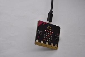
Project 7: Accelerometer
1. Project Introduction:
The Micro: Bit main board V2 has a built-in LSM303AGR gravity acceleration sensor, also known as accelerometer, with a resolution of 8/10/12 bits. The code section sets the range to 1g, 2g, 4g, and 8g.
We often use accelerometer to detect the status of machines.
In this project, we will introduce how to measure the position of the board with the accelerometer. And then have a look at the original three-axis data output by the accelerometer.
2. Components Needed:
Micro:bit main board V2 *1
USB cable*1
3. Connection Diagram:
Attach the Micro:bit main board V2 to your computer via the USB cable.
4. Test Code 1:
5. Test Results 1:
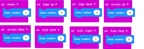
After uploading the test code to micro:bit main board V2 and powering the board via the USB cable, if we shake the Micro: Bit main board V2, no matter at any direction, the LED dot matrix displays the digit “1”.
When it is kept upright (put its logo above the LED dot matrix)as shown below, the number 2 will show.
When it is kept upside down( make its logo below the LED dot matrix) , it will show as below.
When it is placed still on the desk, showing its front side, the number 4 appears.
When it is placed still on the desk, showing its back side, the number 5 will exhibit.
When the board is tilted to the left , the LED dot matrix shows the number 6 as shown below.
When the board is tilted to the right , the LED dot matrix displays the number 7 as shown below
When the board is knocked to the floor, this process can be considered as a free fall and the LED dot matrix shows the number 8. (Please note that this test is not recommended for it may damage the main board.)
Attention: if you’d like to try this function, you can also set the acceleration to 3g, 6g or 8g. But still ,we don not recommend.
6. Test Code 2:
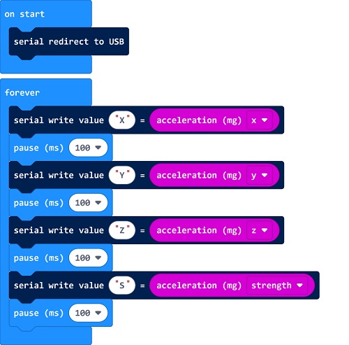
7. Test Results 2:
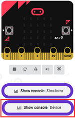
Upload test code to micro:bit main board V2, power the main board via the USB cable, and click“Show console Device”.
After referring to the MMA8653FC data manual and the hardware schematic diagram of the Micro: Bit main board V2, the accelerometer coordinate of the board are shown in the figure below:
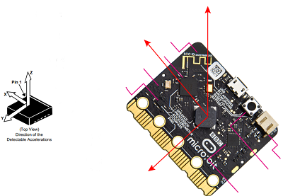
The following interface shows the decomposition value of acceleration in X axis, Y axis and Z axis respectively, as well as acceleration synthesis (acceleration synthesis of gravity and other external forces).
If you’re running Windows 7 or 8 instead of Windows 10, via Google Chrome won’t be able to match devices. You’ll need to use the CoolTerm serial monitor software to read data.
You could open CoolTerm software, click Options, select SerialPort, set COM port and baud rate to 115200 (after testing, the baud rate of USB SerialPort communication on Micro: Bit main board V2 is 115200), click OK, and Connect. The CoolTerm serial monitor shows the data of X axis, Y axis and Z axis , as shown in the figures below :
Project 8: Light Detection
1. Project Introduction:
In this project, we focus on the light detection function of the Micro: Bit main board V2. It is achieved by the LED dot matrix. And it can be viewed as a photosensor.
2. Components Needed:
Micro:bit main board V2 *1
USB cable*1
3. Connection Diagram:
Attach the Micro:bit main board V2 to your computer via the USB cable.
4. Test Code:
5. Test Results:
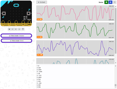
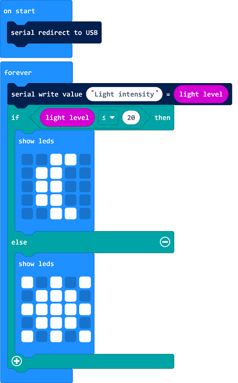
Upload the test code to micro:bit main board V2, power the board via the USB cable and click “Show console Device”.
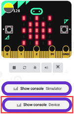
When the LED dot matrix is covered by hand, the value of light intensity showed is approximately 0; when the LED dot matrix is exposed to light, the value displayed gets bigger with the light intensity as shown below.
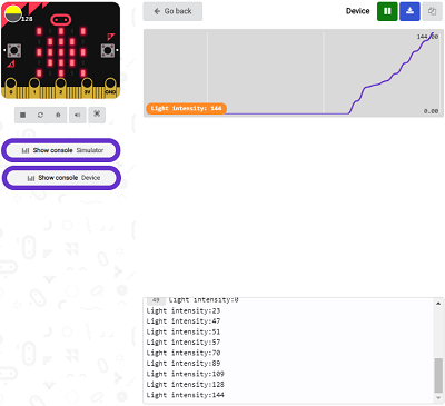
The 20 in the code is an arbitrary value of light intensity. If the current light level is less than or equal to 20, the moon will appear on the LED dot matrix. If it’s bigger than 20, the sun will appear.
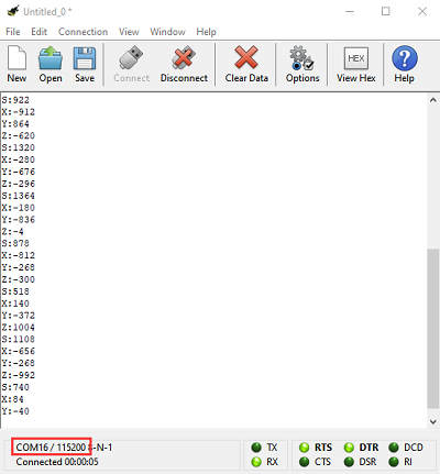
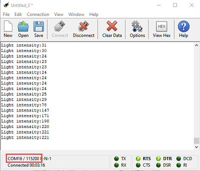
If you’re running Windows 7 or 8 instead of Windows 10, via Google Chrome won’t be able to match devices. You’ll need to use the CoolTerm serial monitor software to read data.
You could open CoolTerm software, click Options, select SerialPort, set COM port and baud rate to 115200 (after testing, the baud rate of USB SerialPort communication on Micro: Bit main board V2 is 115200), click OK, and Connect. The CoolTerm serial monitor shows the value of light intensity , as shown in the figures below :
Project 9: Speaker
1. Project Introduction:
The Micro: Bit main board V2 has an built-in speaker, which makes adding sound to the programs easier. We can program the speaker to air all kinds of tones, such as playing the song “Ode to Joy” .
2. Components Needed:
Micro:bit main board V2 *1
USB cable*1
3. Connection Diagram:
Attach the Micro:bit main board V2 to your computer via the USB cable.
4. Test Code 1:
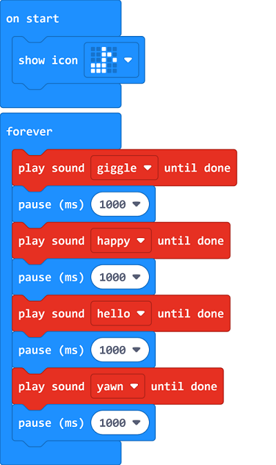
5. Test Results 1 :
After uploading the test code to micro:bit main board V2 and powering the board via the USB cable, the speaker utters sound and the LED dot matrix shows the logo of music.
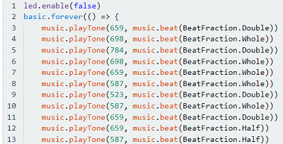
6. Test Code 2:
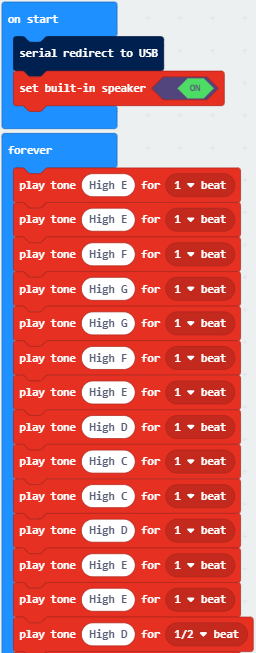
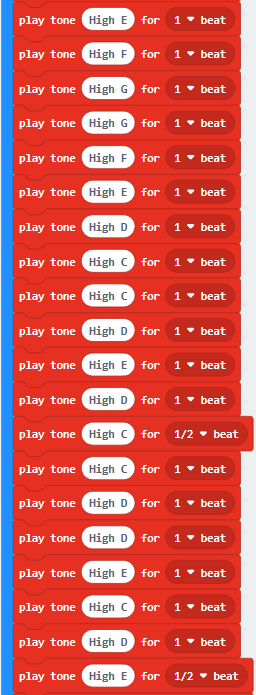
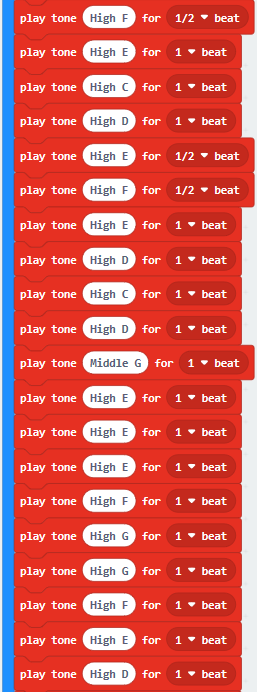
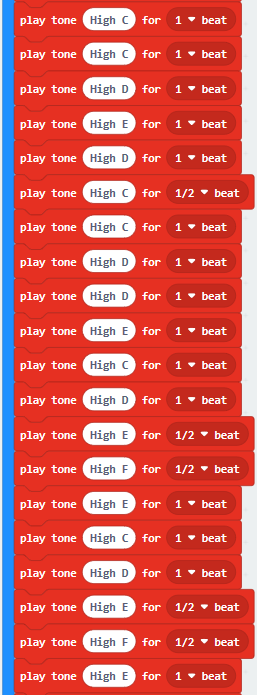
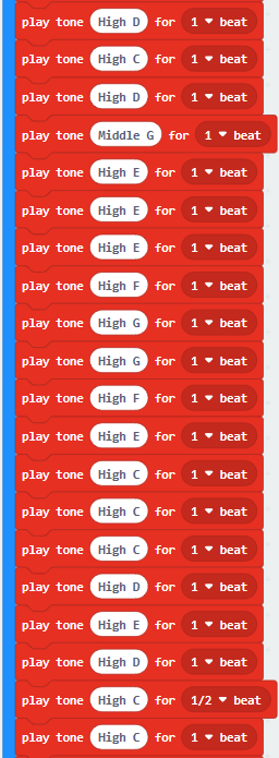
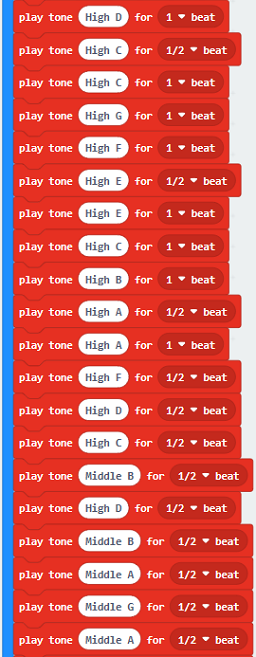
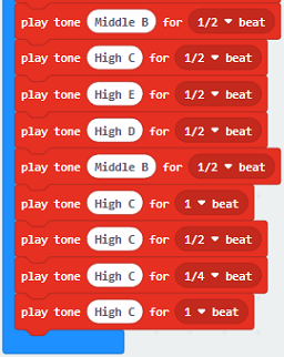
The musical score of the song “Ode to Joy” is as follows:

Link to more information about musical notation: https://en.wikipedia.org/wiki/Numbered_musical_notation
7. Test Results 2:
After uploading the test code to micro:bit main board V2 and powering the board via the USB cable, the board airs the song “Ode to Joy”.
Project 10: Touch-sensitive Logo
1. Project Introduction:
The Micro: Bit main board V2 is equipped with a golden touch-sensitive logo, which can act as an input component and function like an extra button.
It contains a capacitive touch sensor that senses small changes in the electric field when pressed (or touched), just like your phone or tablet screen do. When you press it , you can activate the program.
2. Components Needed:
Micro:bit main board V2 *1
USB cable*1
3. Connection Diagram:
Attach the Micro:bit main board V2 to your computer via the USB cable.
4. Test Code:
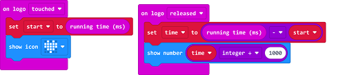
5. Test Results:
After uploading the test code to micro:bit main board V2 and powering the board via the USB cable, the LED dot matrix exhibits the heart pattern when the touch-sensitive logo is pressed or touched and displays digit when the logo is released.
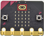
Project 11: Microphone

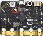
1. Project Introduction:
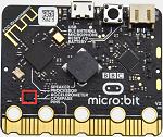
The Micro: Bit main board V2 is built with a microphone which can test the volume of ambient environment. When you clap, the microphone LED indicator will turn on. Since it can measure the intensity of sound, you can make a noise scale or disco lighting changing with music. The microphone is placed on the opposite side of the microphone LED indicator and in proximity with holes that lets sound pass. When the board detects sound, the LED indicator lights up.
2. Components Needed:
Micro:bit main board V2 *1
USB cable*1
3. Connection Diagram:
Attach the Micro:bit main board V2 to your computer via the USB cable.
4. Test Code 1:
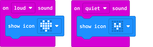
5. Test Results 1:
After uploading test code to micro:bit main board V2 and powering the board via the USB cable, the LED dot matrix displays pattern “”when you claps and pattern when it is quiet around.
6. Test Code 2:
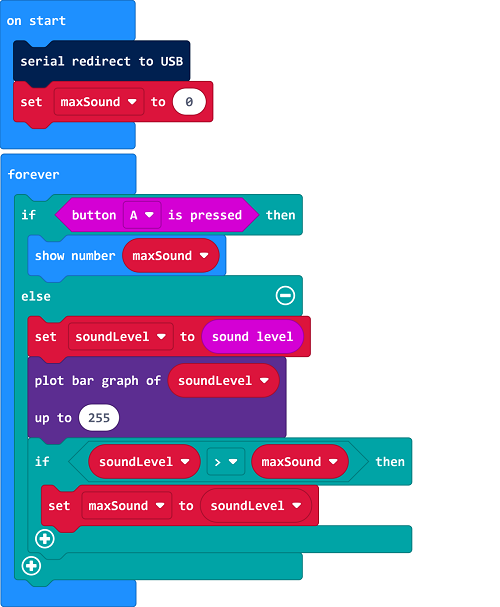
7. Test Results 2:
Upload test code to micro:bit main board V2, power the board via the USB cable and click “Show console Device”as shown below.
When the sound is louder around, the sound value shows in the serial port gets bigger as shown below.
What’s more, when pressing the button A, the LED dot matrix displays the value of the biggest volume( please note that the biggest volume can be reset via the Reset button on the other side of the board ) while when clapping, the LED dot matrix shows the pattern of the sound.
Project 12: Bluetooth Data Reading
1. Project Introduction:
The Micro: Bit main board V2 comes with a nRF52833 processor (with built-in Bluetooth 5.1 BLE(Bluetooth Low Energy) device) and a 2.4GHz antenna for Bluetooth wireless communication and 2.4GHz wireless communication. With the help of them, the board is able to communicate with a variety of devices with tool Bluetooth, including smart phones and tablets.
In this project, we mainly concentrate on the Bluetooth wireless communication function of this main board. Linked with Bluetooth, it can transmit code or signals. To this end, we should connect an Apple device (a phone or an iPad) to the board.
Since setting up Android phones to achieve wireless transmission is similar to that of Apple devices, no need to illustrate again.
2. Preparation
Attachment of the Micro:bit main board V2 to your computer via the USB cable.
An Apple device (a smart phone or an iPad) or an Android device;
3. Procedures:
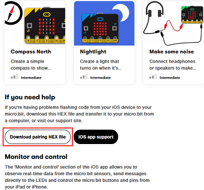
For Apple devices, enter this link https://www.microbit.org/get-started/user-guide/ble-ios/ with your computer first, and then click“Download pairing HEX file”to download the Micro: Bit firmware to a folder or desk, and upload the downloaded firmware to the Micro: Bit main board V2.
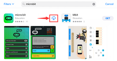
Search“micro bit”in your App Store to download the APP micro:bit.
Connect your Apple device with Micro: Bit main board V2:
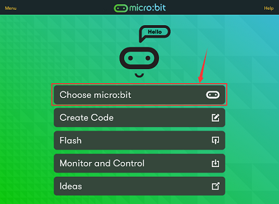
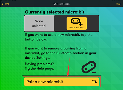
Firstly, turn on the Bluetooth of your Apple device and open the APP micro:bit to select item “Choose micro:bit”to start pairing Bluetooth.
Please make sure that the Micro: Bit main board V2 and your computer are still linked via the USB cable.
Secondly, click “Pair a new micro:bit”;
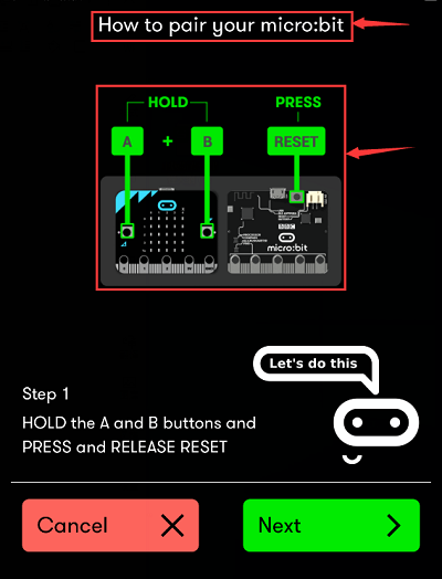
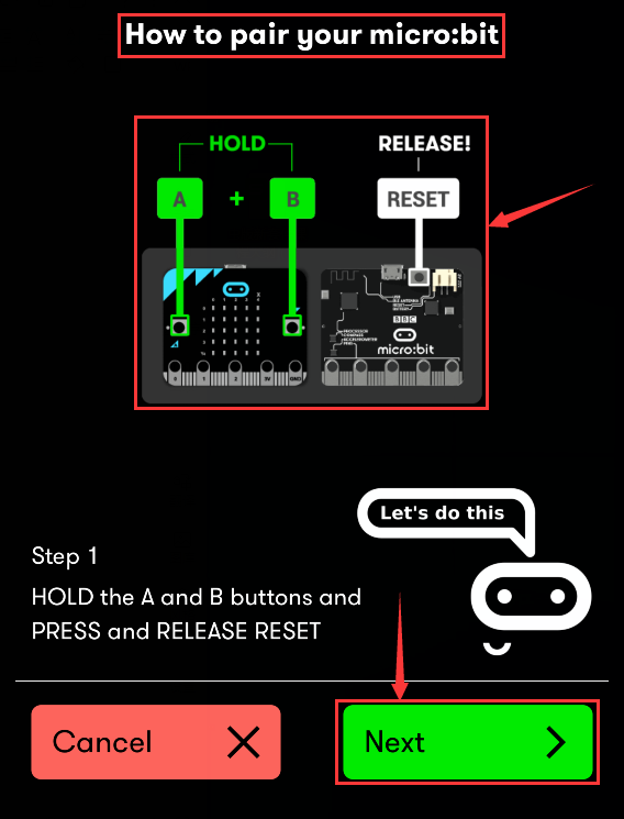
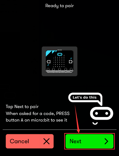
Following the instructions to press button A and B at the same time(do not release them until you are told to) and press Reset & Power button for a few seconds.
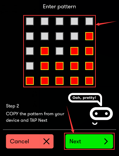
Release the Reset & Power button, you will see a password pattern shows on the LED dot matrix. Now , release buttons A and B and click “Next”.
Set the password pattern on your Apple device as the same pattern showed on the matrix and click “Next”.
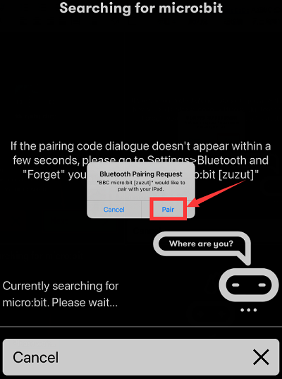
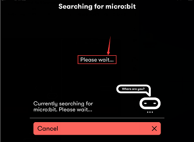
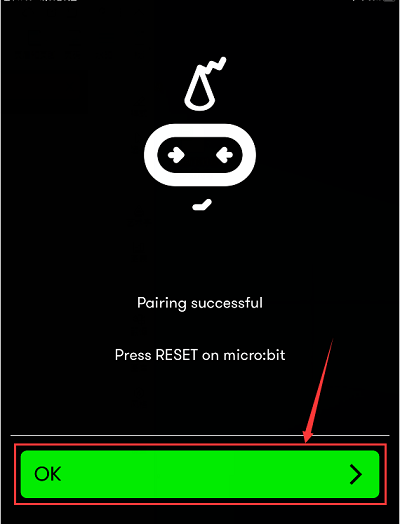
Still click “Next” and a dialog box props up as shown below. Then click “Pair”. A few seconds later, the match is done and the LED dot matrix displays the “√” pattern.
After the match with Bluetooth, write and upload code with the App.
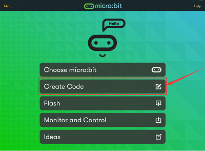
Click“Create Code”to enter the programming page and write code.
Click  and the box
 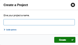 appears, and then select “Create √”.
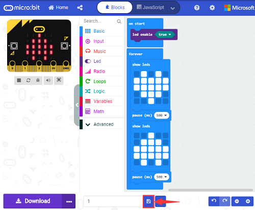
Name the code as“1”and click  to save it.
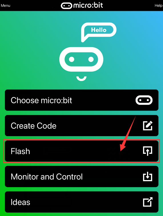
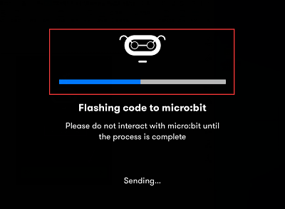
Click the third item “Flash” to enter the uploading page. The default code program for uploading is the one saved just now and named “1” and then click the other “Flash” to upload the code program “1”.
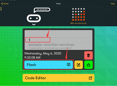
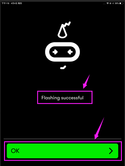
If the code is uploaded successfully a few seconds later, the App will emerge as below and the LED dot matrix of the Micro: Bit main board V2 will exhibit a heart pattern.
Project 13: LED Blinks
1. Project Introduction:
The LED blink is one of the most basic experiments. In the above example use of micro:bit, we have mentioned the 25 LED display of micro:bit. In this project, you will learn how to control an LED blink using a keyestudio digital white LED module and a micro:bit sensor shield. Before testing, you should first turn off the 5*5 LED function of micro:bit.
2. Components Needed:
Micro:bit main board*1
Keyestudio Micro:bit sensor V2 shield*1
USB Cable*1
keyestudio Digital White LED Module*1
DuPont jumper wire*3
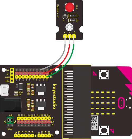
3. Connection Diagram:

4. Test Code:
5. Test Results:
Hook up the components, plug in power and download code to the micro:bit you will see an LED blink on the module, with an interval about one second.
Project 14: LED Breathes
1. Project Introduction:
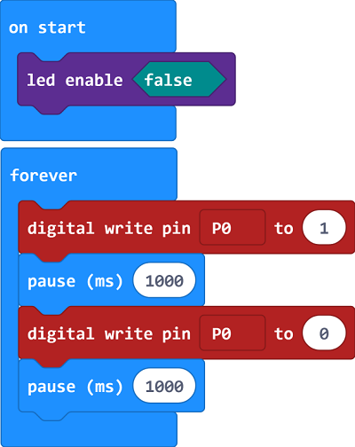
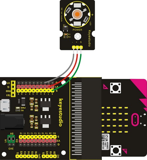
The light breath experiment is a little bit similar to the previous project. This time we connect the keyestudio LED module to the sensor shield. Connect the Signal pin of LED module to P0 of micro:bit. From the Pinout diagram of micro:bit, you can get the P0 can be used as Analog IN.
This lesson you will learn how to control the brightness of LED on the module, gradually becoming brighter and dimming, just like the LED is breathing.
2. Components Needed:
Micro:bit main board*1
Keyestudio Micro bit Sensor V2 Shield*1
USB Cable*1
keyestudio White LED Module*1
DuPont jumper wires
3. Connection Diagram
4. Test Code
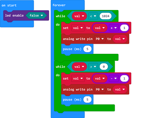
5. Test Results
Hook up the components, plug in power and download code to the micro:bit you should finally see an LED on the module gradually become brighter, then gradually dim, circularly just like the LED is breathing.
Project 15: LED Blinks and Breathes
1. Project Introduction:
In this project, we combine the project 13 and project 14. You will learn how to control the LED on the module blink for two times, then breath for two times, circularly. This time we use keyestudio 3W LED module, which has high brightness and can be used as illumination.
2. Components Needed:
Micro:bit main board*1
Keyestudio Micro bit Sensor V2 Shield*1
USB Cable*1
keyestudio 3W LED Module*1
DuPont jumper wires
3. Connection Diagram
4. Test Code
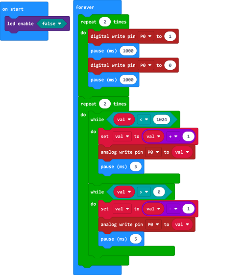
5. Test Results
Hook up the components, plug in power and download code to the micro:bit you should see the LED on the module firstly blink two times, then breath two times, circularly.
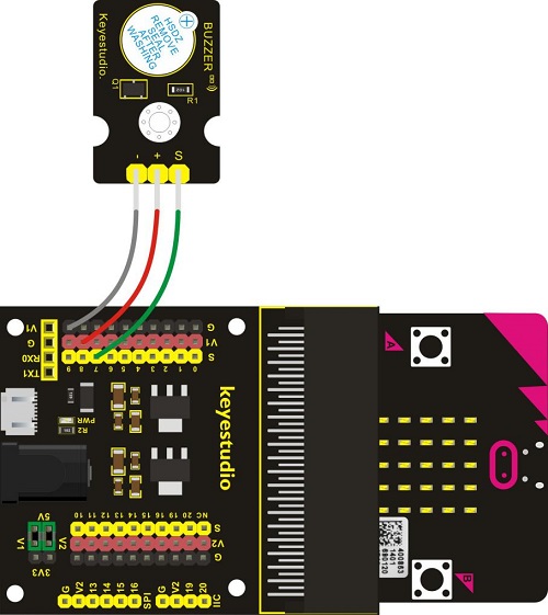
Project 16: Make A Sound
1. Project Introduction:
We can use Micro:bit to make many interactive works of which the most commonly used is acoustic-optic display. All the previous projects have something to do with LED. However, the circuit in this experiment can produce sound. Normally, the experiment is done with a buzzer or a speaker because buzzer is more simpler and easier to use.
There are two kinds of buzzer, active buzzer and passive buzzer. In this lesson, we will use Micro:bit to drive an active buzzer. The active buzzer inside has a simple oscillator circuit which can convert constant direct current into a certain frequency pulse signal. Once active buzzer receives a high level, it will produce an audible beep.
2. Components Needed:
Micro:bit main board*1
Keyestudio Micro bit Sensor V2 Shield*1
USB Cable*1
keyestudio Active Buzzer*1
DuPont jumper wires
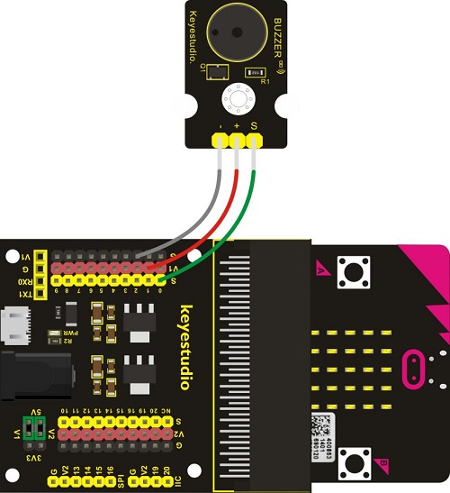
3. Connection Diagram
4. Test Code
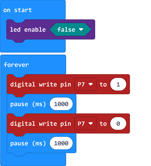
5. Test Results
Hook up the components, plug in power and download code to the micro:bit you should hear the buzzer module sound and then stop, circularly. It seems like the sound is interrupted.
Project 17: Play Music
1. Project Introduction:
In this project, you will learn how to play music with keyestudio passive buzzer module. We are going to complete two experiments.
One is to directly control the High and Low level input of micro:bit P0 end, set two square waves to control the buzzer sound. The other is to use the software’s own function, input the square waves of different frequencies and different lengths on the P0 end. Finally make the buzzer module play the song “Ode to Joy”.
(The input PIO port can only be P0, can not be other interfaces).
2. Components Needed:
Micro:bit main board*1
Keyestudio Micro bit Sensor V2 Shield*1
USB Cable*1
Keyestudio Passive Buzzer Module*1
DuPont jumper wire
3. Connection Diagram
4. Test Code 1
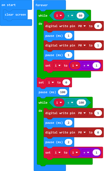
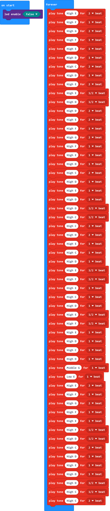
5. Code 2
Note: on the MakeCode Block webpage, click the icon  , you can see the frequency of each tone as follows.
6. Test Results
Done wiring and powered up, send the code 1 to micro:bit, you should hear two sounds produced from passive buzzer circularly. If send the code 2 to micro:bit, the buzzer will play the song Ode To Joy! Really amazing. Right? You can try to change the tone to play other music.
Project 18: Change Colors
1. Project Introduction:
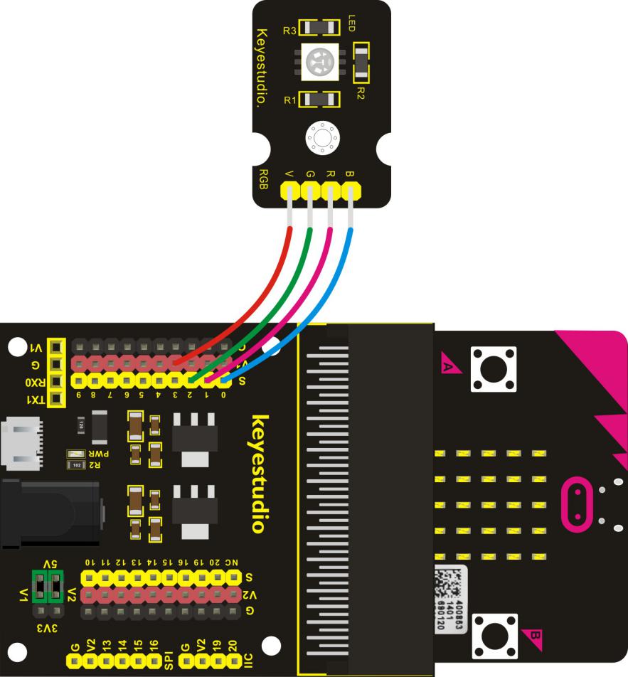
In this project, we will use a keyestudio RGB LED module. This Common Anode RGB LED module is a fun and easy way to add some color to your projects. In our program, we will connect the RGB module to micro:bit, then control the P0, P1, P2 Analog Input of micro:bit main board. You will learn how to control the RGB LED on the module firstly show three colors (Red, Green and Blue), then quickly change the color state.
2. Components Needed:
Micro:bit main board*1
Keyestudio Micro bit Sensor V2 Shield*1
USB Cable*1
keyestudio RGB LED Module*1
DuPont jumper wire*4
3. Connection Diagram
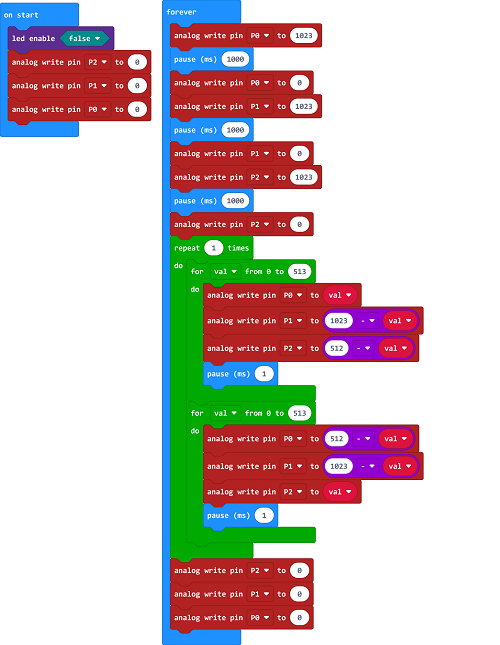
4. Test Code
5. Test Results
Hook up the components, plug in power and download code to the micro:bit you should see the RGB module firstly show three colors, separately red, green and blue light. Then change the color quickly and circularly.
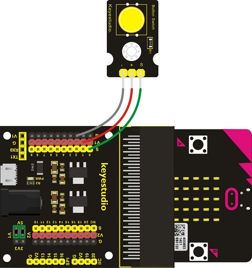
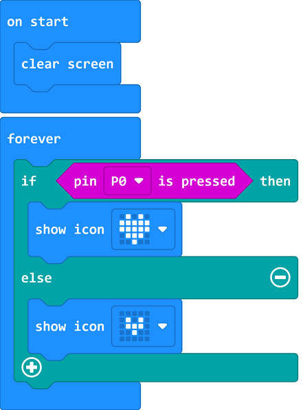
Project 19: Button Control
1. Project Introduction:
When design the circuit, button switch is a commonly used component. The micro:bit main board has two built-in buttons, however, sometimes still need to use external button when design the circuit. So in this project, you will learn how to use our push button module to control 5*5 LED of micro:bit display different images.
2. Components Needed:
Micro:bit main board*1
Keyestudio Micro bit Sensor V2 Shield*1
USB Cable*1
Keyestudio Digital Push Button*1
DuPont jumper wires
3. Connection Diagram
4. Test Code
5. Test Results
Wire up components, upload code, plug in power and press digital button module. Then the micro:bit will show. If the digital button module is not touched, image will be displayed.
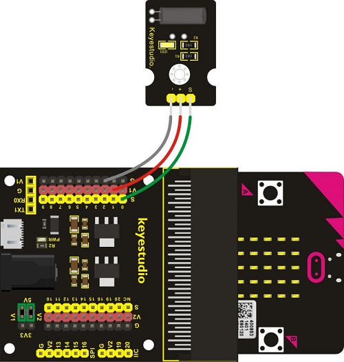
Project 20: Tilt Control
1. Project Introduction:
When design the circuit, sometimes you will need to test whether an object is tilted left or right, so in this case you can use our tilt sensor. In this project, you will learn how to use our digital tilt sensor to control 5*5 LED of micro:bit display different images.
2. Components Needed:
Micro:bit main board*1
Keyestudio Micro bit Sensor V2 Shield*1
USB Cable*1
keyestudio Digital Tilt Sensor*1
DuPont jumper wires
3. Connection Diagram
4. Test Code

5. Test Results
Done wiring and powered up, send the code to micro:bit. When the sensor is tilted to the left, the LED matrix will show ; however, if the sensor is tilted to the right, imagewill be displayed.
Project 21: Light Interrupter
1. Project Introduction:
In daily life, we often need to implement the function of counting and speed measurement. How to achieve these functions? You can easily match photo-interrupter module with microcontroller via code debugging. In this lesson, we connect a keyestudio photo-interrupter module to micro:bit sensor shield, then control 5*5 LED of micro:bit show different images.
2. Components Needed:
Miro:bit main board*1
Keyestudio Micro bit Sensor V2 Shield*1
USB Cable*1
Keyestudio Photo Interrupter Module*1
DuPont jumper wires
3. Connection Diagram
4. Test Code

5. Test Results
Wire up the components, upload code and plug in power. When you cover the notch of sensor with a piece of paper, the image will be shown ; on the contrary, the image will be displayed.
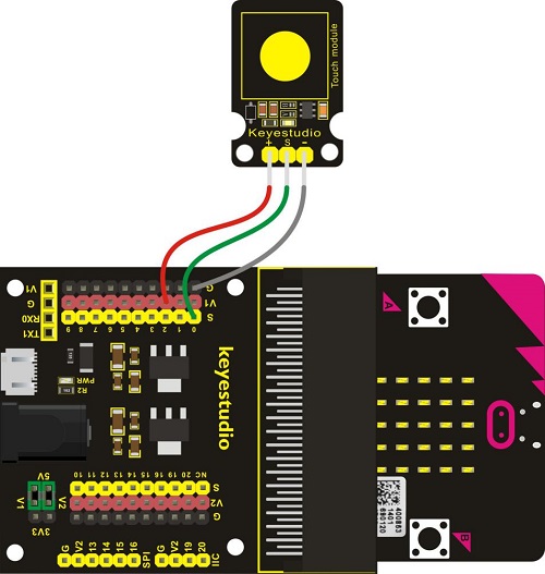
Project 22: Capacitive Touch
1. Project Introduction:
In the above project 8, we have done a button control experiment. This time, we are going to replace the button switch with a capacitive touch sensor. In this project, you will learn how to use Keyestudio touch sensor to control 5*5 LED of micro:bit show different images.
2. Components Needed:
Micro:bit main board*1
Keyestudio Micro bit Sensor V2 Shield*1
USB Cable*1
Keyestudio Capacitive Touch Sensor*1
DuPont jumper wires
3. Connection Diagram
4. Test Code

5. Test Results
Wire up the components, upload code and plug in power. If you touch the sensitive area, the micro:bit will display; otherwise, imagewill be shown.
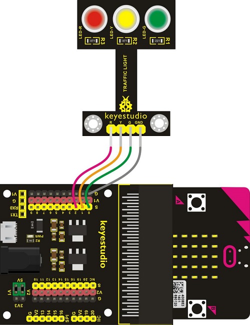
Project 23: Traffic Light
1. Project Introduction:
When walking at the crossroad, you can see the traffic light command the orderly movement of pedestrians and vehicles. So how is the traffic light controlled to operate? In this project, we will connect a traffic light module to our sensor shield, controlling traffic light blink with micro:bit. You will learn how to simulate the running of traffic light.
2. Components Needed:
Micro:bit main board *1
Keyestudio Micro bit Sensor V2 Shield *1
USB Cable *1
Keyestudio Traffic Light Module *1
DuPont jumper wires
3. Connection Diagram
4. Test Code
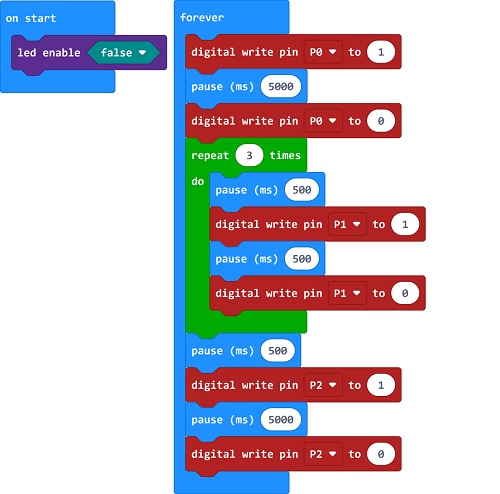
5. Test Results
Done wiring and powered up, send the code to micro:bit, eventually you should see the green LED lights 5 seconds then off, and yellow LED starts to blink 3 times with an interval of 0.5 second, then off, followed by red LED lights up for 5 seconds then off. Up to this moment, green LED lights again, forming a loop cycle.
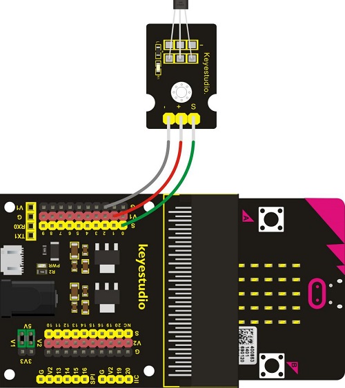
Project 24: Magnetic Detection
1. Project Introduction:
In this project, you will learn how to use our hall magnetic sensor to control 5*5 LED of micro:bit display different images.
The main component used in this sensor is A3144E. This hall magnetic sensor can be used to detect a magnetic field, outputting Digital signal. It can sense the magnetic materials within a detection range up to 3cm.
Note that it can only detect whether exists a magnetic field nearby but can not detect the strength of magnetic field.
2. Components Needed:
Micro:bit main board*1
Keyestudio Micro bit Sensor V2 Shield*1
USB Cable*1
keyestudio Hall Magnetic Sensor*1
DuPont jumper wires
3. Connection Diagram
4. Test Code

5. Test Results
Wire up the components, upload code and plug in power. When the sensor is close to the magnetic field,the micro:bit will show,otherwise, the image will be shown.
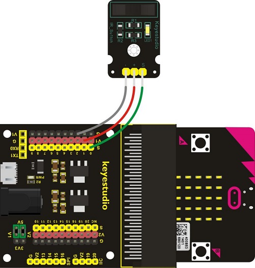
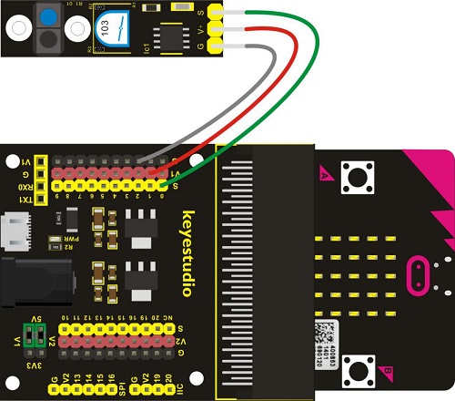
Project 25: Follow Black Line
1. Project Introduction:
When doing DIY experiments, you perhaps see such a smart car that can follow a black line and not beyond the black area. How can achieve this? Yeah, make use of line tracking sensors. In this project, we will use a tracking sensor combined with micro:bit to detect an object or a black line. You can get the result shown on the LED display of micro:bit.
The tracking sensor is actually an infrared sensor, which can detect a black line. The component used in the sensor is TCRT5000 infrared tube.
Its working principle is to use the different reflectivity of infrared light to the color, then convert the strength of the reflected signal into a current signal.
When sensor detects a black line, the infrared rays are not emitted or the intensity of emitted ray back are not sufficiently strong, so that the sensor’s signal terminal outputs a High level. Otherwise, output a Low level.
2. Components Needed:
Micro:bit main board*1
Keyestudio Micro bit Sensor V2 Shield*1
USB Cable*1
keyestudio Hall Magnetic Sensor*1
DuPont jumper wires
3. Connection Diagram
4. Test Code
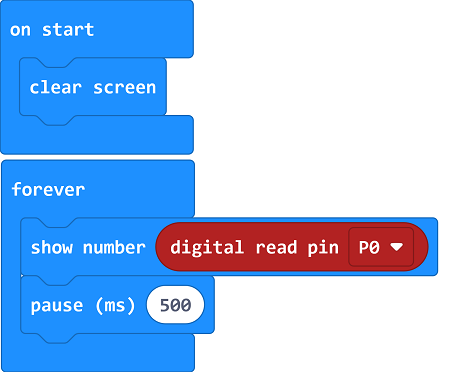
5. Test Results
Done wiring and powered up, send the code to micro:bit. When sensor detects no object or detects a black line, the infrared rays are not emitted or the intensity of emitted ray back are not sufficiently strong, so that the sensor’s signal terminal will output a High level, LED on the micro:bit will show the number 1. Or else show the number.
Note: on the module, you can rotate the potentiometer to make the LED between on and off state. The sensitivity is the best.
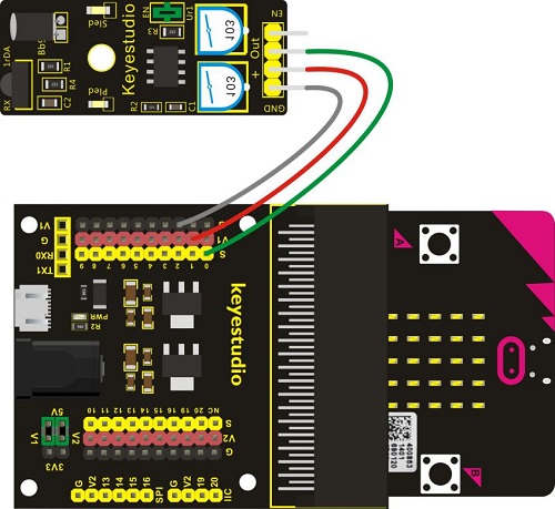
Project 26: Obstacle Avoidance
1. Project Introduction:
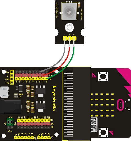
When doing DIY experiments, you perhaps see such a smart car that can automatically avoid an obstacle ahead. How can achieve this? Yeah, make use of infrared obstacle avoidance sensors. In this project, we will use a obstacle sensor combined with micro:bit to detect an object ahead and automatically avoid it. You can get the result shown on the LED display of micro:bit.
2. Components Needed:
Micro:bit main board*1
Keyestudio Micro:bit Sensor V2 Shield*1
USB Cable*1
keyestudio Obstacle Detector Sensor*1
DuPont jumper wires
3. Connection Diagram
4. Test Code
5. Test Results
Wire up the components, upload code and plug in power. When sensor detects an object ahead, its signal terminal will output a Low level, and LED matrix on the micro:bit will show the number 0. Or else show the number 1.
Note: for obstacle sensor, you can rotate the two potentiometers on the sensor to adjust its sensitivity. Rotate the potentiometer near the infrared transmitter tube clockwise to the end, and then adjust the potentiometer near the infrared receiver. Sled light is turned off and keeps the critical point to be lit. The sensing distance is the longest.
The effective distance of the sensor is within 2-40 cm.
Project 27: Someone Comes
1. Project Introduction:
You may see such a lens in a film or television. When someone wants to attack a target, but not close to the target, they were directly found and the alarm sounded. When some special forces go to the target, they will be covered with moist mud, so that they will not be discovered by the other party.
Why?
Originally, the human body will emit a certain wavelength of infrared rays of about 10um. The relevant sensors are installed near the targets that are being attacked to sense the infrared rays emitted by the human body and then alarm. After the mud is applied, the sensors can not sense the infrared rays emitted by the human body.
In this project, you will learn how to use a PIR motion sensor and micro:bit to detect whether there is someone move nearby. Finally show the different images on 25 LED matrix of micro:bit.
2. Components Needed:
Micro:bit main board*1
Keyestudio Micro bit Sensor V2 Shield*1
USB Cable*1
keyestudio PIR Motion Sensor*1
Dupont jumper wires
3. Connection Diagram
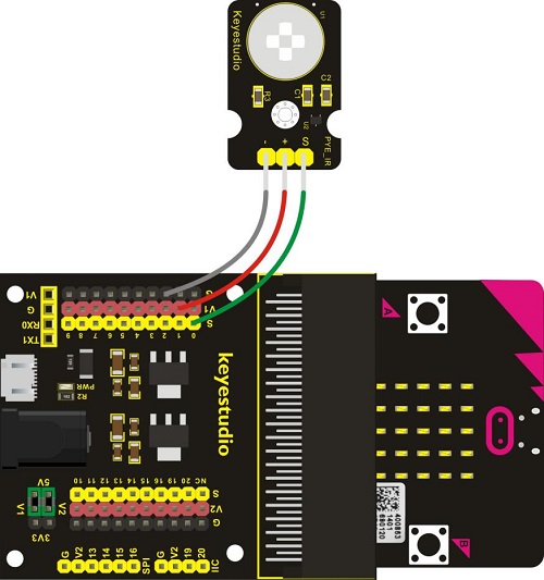
Note: when you adjust the PIR motion sensor clockwise, the detected range will increase; on the contrary, the sensed distance will reduce.
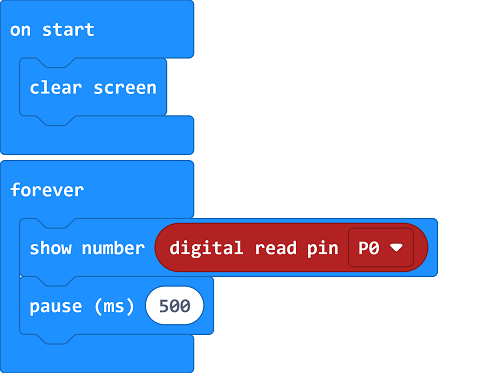
4. Test Code
5. Test Results
Wire up the components, upload code and plug in power. When the sensor detects the people moving, the micro:bit will show; otherwise, the imagewill be shown.
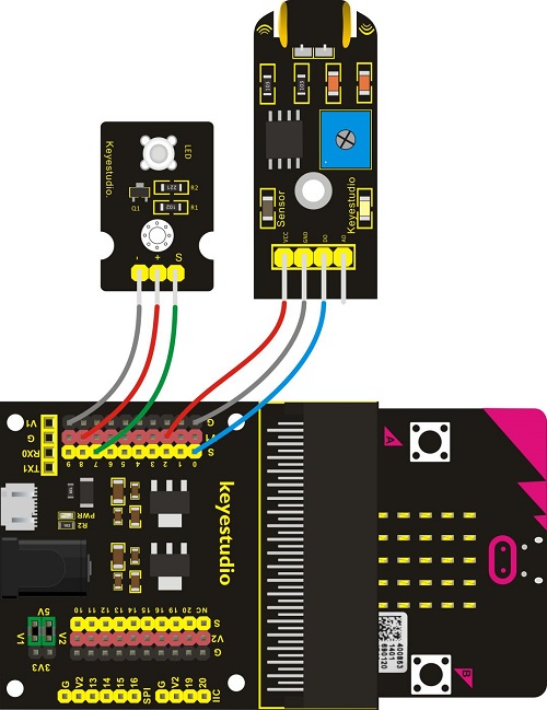
Project 28: Fire Alarm
1. Project Introduction:
In daily life, it is often seen that a fire broke out without any precaution. It will cause great economic and human loss. So how can we avoid this situation? Right, install a flame sensor and a speaker in those places that easily break out a fire. When the flame sensor detects a fire, the speaker will alarm people quickly to put out the fire.
In this project, you will learn how to use a flame sensor and an active buzzer module to simulate the fire alarm system.
This flame sensor can be used to detect fire or other light sources with wavelength stands at 760nm ~ 1100nm. Its detection angle is about 60°. You can rotate the potentiometer on the sensor to control its sensitivity. Adjust the potentiometer to make the LED at the critical point between on and off state. The sensitivity is the best.
2. Components Needed:
Micro:bit main board*1
Keyestudio Micro bit Sensor V2 Shield*1
USB Cable*1
keyestudio Flame Sensor*1
keyestudio Active Buzzer Module*1
Dupont jumper wires
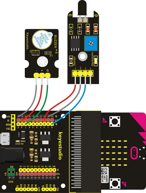
3. Connection Diagram
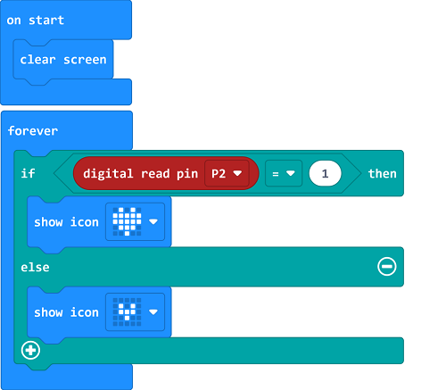
4. Test Code

5. Test Results
Wire up the components, upload code and plug in power. When the sensor detects the flame, the buzzer will chime; otherwise, it won’t emit a sound.
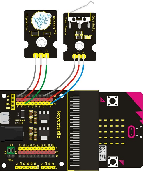
Project 29: Crash Sensor
1. Project Introduction:
During the DIY, we may usually use a machine-3D printer. You can use it to print any elements with different structures. And limit switch is essential in the printing, which mainly provides the information whether XYZ axis of printer reach the boundary point.
Keyestudio crash sensor is a limit switch, available for 3D printer. It is in essence the same as button module. When printer reaches the top to crash the spring plate of module, module outputs Low level. If loosen the spring plate, module outputs High.
In this lesson, you will learn how to use a collision sensor and a digital buzzer module to simulate the 3D printer limit.
2. Components Needed:
Micro:bit main board*1
Keyestudio Micro bit Sensor V2 Shield*1
USB Cable*1
Keyestudio Crash Sensor*1
Keyestudio Digital Buzzer Module*1
Dupont jumper wires
3. Connection Diagram
4. Test Code
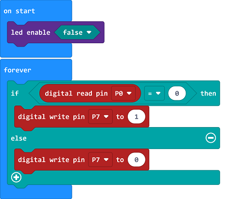
5. Test Results
Wire up the components, upload code and plug in power. When the spring plate of crash sensor is pressed, the buzzer will chime, otherwise it won’t emit a sound.
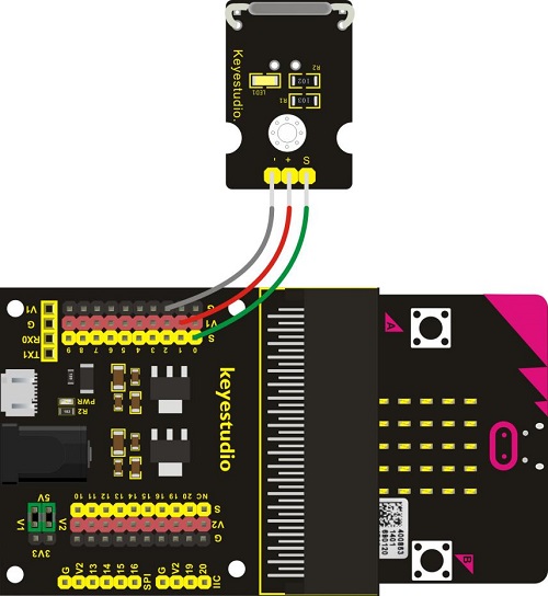
Project 30: Magnetic Switch
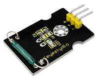
1. Project Introduction:
In this project, you will learn how to use a keyestudio reed switch module and micro:bit to detect the magnetic field. Finally show the result on the 25 LED matrix of micro:bit. Actually in the project 13, we have used a hall magnetic sensor to detect whether there is magnetic field nearby.
So what is the differences between hall magnetic sensor and reed switch module? You can check it in component introduction below.
2. Components Needed:
Micro:bit main board*1
Keyestudio Micro bit Sensor V2 Shield*1
USB Cable*1
Keyestudio Reed Switch Module*1
Dupont jumper wires
3. Connection Diagram
4. Test Code

5. Test Results
Wire up the components, upload code and plug in power. When the module is close to the magnetic field, the micro:bit will display; if not, the imagewill be shown.
Project 31: Relay Module
1. Project Introduction:
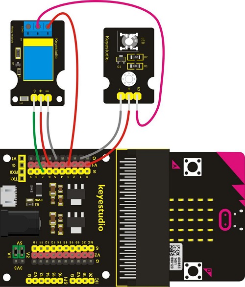
In daily life, we generally use 220V AC to drive the electrical equipment. Sometimes we will use the switch to control the electrical appliance. If directly connect the switch to the 220V AC circuit, once electric leakage happened, people are in danger. Considered with safety, we particularly design this keyestudio single relay with terminal block of NO (normally open) and NC (normally closed), which is active at High.
In this project, you will learn how to use our relay module and micro:bit to control an LED module on and off. (note that for easy wiring, the circuit does not add 220V voltage, still use 5V.)
2. Components Needed:
Micro:bit main board*1
Keyestudio Micro bit Sensor V2 Shield*1
USB Cable*1
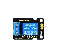
Keyestudio Single Relay Module*1
Keyestudio White LED Module
Dupont jumper wires
3. Connection Diagram
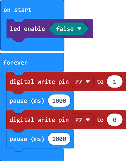
4. Test Code
5. Test Results
Wire up the components, upload code and plug in power.When relay module is connected or disconnected, the LED module will be on and off, with an interval of 1s.
Project 32: Ultrasonic Ranging
1. Project Introduction:
Ultrasonic sensor is great for all kind of projects that need distance measurements, avoiding obstacles as examples.
In this project, you will learn how to use a ultrasonic module and micro:bit to detect the distance between the module and an obstacle ahead.
It includes an ultrasonic transmitter, receiver and control circuit.
Ultrasonic module will emit the ultrasonic waves after trigger signal. When the ultrasonic waves encounter an object and are reflected back, the module outputs an echo signal, so it can determine the distance of object from the time difference between trigger signal and echo signal.
2. Components Needed:
Micro:bit main board*1
Keyestudio Micro bit Sensor V2 Shield*1
USB Cable*1
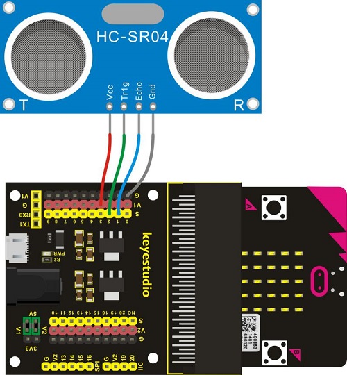
Keyestudio Ultrasonic Module*1
Dupont jumper wires
3. Connection Diagram
4. Test Code 1
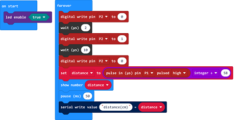
5. Code 2
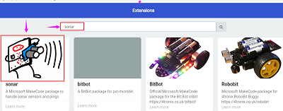
Set the code with libraries.Search sonar
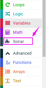
Check Sonar block in the Makecode editor.
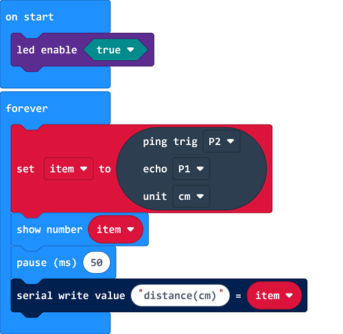
6. Test Results
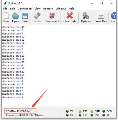
Connect micro:bit to computer via USB cable and transfer code to micro:bit. Open CoolTerm, click Options and select SerialPort, set COM port and baud rate(115200). Click OK and Connect.
The detected distance value can be shown on the micro:bit and CoolTerm monitor.
Project 33: Light Brightness
1. Project Introduction:
It is seen that sensors are everywhere in our daily life. Some public street lights automatically light up during the day and automatically go out at night. Why?In fact, those lights make use of a photosensitive element that can measure the brightness of external light.
In the evening, when outside brightness becomes lower, the street light is automatically controlled to be turned on. When it is bright during the day, the street light is automatically turned off.
In this project, you will learn how to use our keyestudio photocell sensor and micro:bit to control the brightness of external light. Show the result on 5*5 LED of micro:bit or serial monitor of CoolTerm software.
2. Components Needed:
Micro:bit main board*1
Keyestudio Micro bit Sensor V2 Shield*1
USB Cable*1
keyestudio Photocell Sensor*1
Dupont jumper wires
3. Connection Diagram

4. Test Code
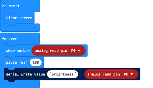
5. Test Results
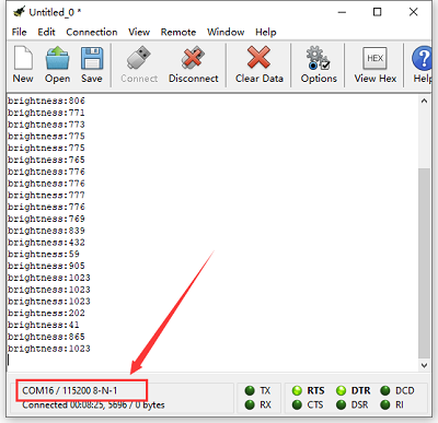
Connect micro:bit to computer via USB cable and transfer code to the micro:bit.Open CoolTerm, click Options and select SerialPort, set COM port and baud rate(115200). Click OK and Connect.
CoolTerm monitor shows the corresponding analog signal, with the light intensity getting weaker, the analog value plummets gradually;otherwise, the analog value will grow and LED will become brighter.
Project 34: Hear Footsteps
1. Project Introduction:
As for those corridor lights, when we walk through the corridor to make a sound, the corridor light will automatically light up, after that, quiet down, the lights are off. Why? Actually inside the lighting circuit, it has installed a sound sensor. When detects the sound, light is turned on, or else LED off.
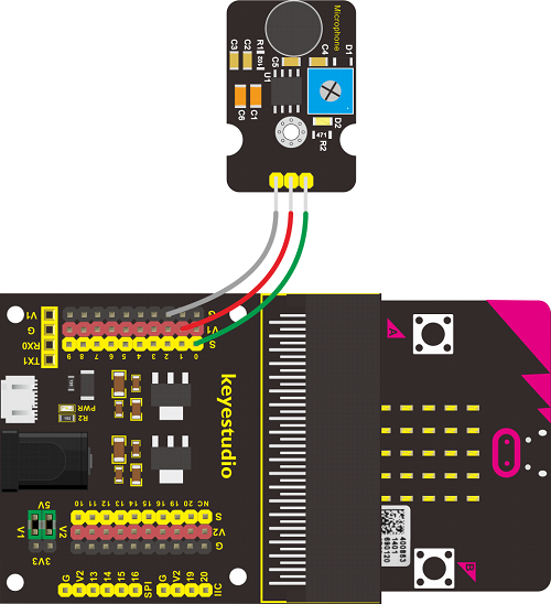
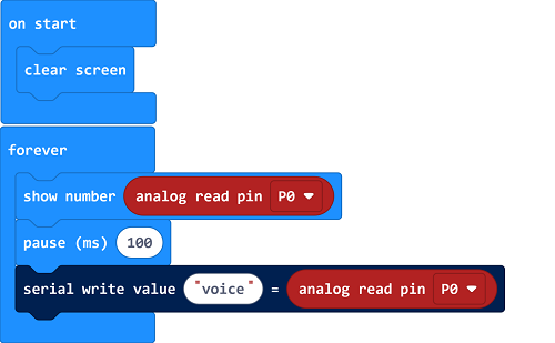
In this lesson, we connect an analog sound sensor to P0 of micro:bit, then detect the outside sound via reading the analog value of P0.
The greater the external sound, the greater the analog value.
You can see the analog value is displayed on the micro:bit LED matrix, or check it from serial monitor of CoolTerm software.
Note: you can rotate the potentiometer to adjust the sound intensity.
2. Components Needed:
Micro:bit main board*1
Keyestudio Micro bit Sensor V2 Shield*1
USB Cable*1
Keyestudio Analog Sound Sensor*1
Dupont jumper wires
3. Connection Diagram
4. Test Code
5. Test Results
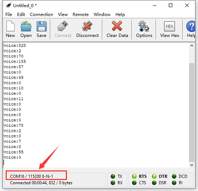
Wire up according to connection diagram. Plug in external power and upload code to micro:bit. Open CoolTerm, click Options and select SerialPort, set COM port and baud rate(115200). Click OK and Connect. You can see the sound value on the micro:bit and monitor.
Project 35: Rotary Potentiometer
1. Project Introduction:
In this experiment, the signal end of keyestudio Analog Rotation Sensor is connected to micro:bit P0. By reading the analog value of P0, rotate the potentiometer, you should see the analog value is changed on the micro:bit LED matrix.
This analog rotation sensor is based on a potentiometer. It actually uses a variable resistor. When rotate the potentiometer, it actually changes the resistance of variable device.
In the experiment, set well the circuit, convert the resistance changes into voltage changes, then input the voltage changes into Analog Input of micro:bit via signal end, getting the analog value via programming.
2. Components Needed:
Micro:bit main board*1
Keyestudio Micro bit Sensor V2 Shield*1
USB Cable*1
Keyestudio Analog Rotation Sensor*1
Dupont jumper wires
3. Connection Diagram
4. Test Code
5. Test Results
Connect micro:bit to computer via USB cable and transfer code to micro:bit. Open CoolTerm, click Options and select SerialPort, set COM port and baud rate(115200). Click OK and Connect.
When you adjust the potentiometer, you will see the detested data on the micro:bit and CoolTerm software.
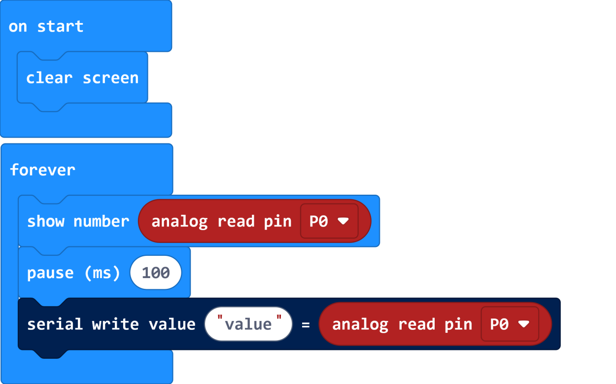
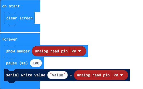
Project 36: Alcohol Content in the Air
1. Project Introduction:
In this project, you will learn how to use an analog Alcohol sensor and micro:bit to detect the alcohol content in the air.
This analog sensor-MQ3 is suitable for detecting the alcohol. It can be used in a breath analyzer. It has a good selectivity because it has higher sensitivity to alcohol and lower sensitivity to Benzine.
The sensitivity can be adjusted by rotating a potentiometer on the sensor.
It has two signal pins, Analog A0 and Digital D0. The higher the alcohol concentration, the higher the A0 value.
When both alcohol concentration and A0 value reach a certain value, D0 changes from low level to high level, which can be controlled by potentiometer.
2. Components Needed:
Micro:bit main board*1
Keyestudio Micro bit Sensor V2 Shield*1
USB Cable*1
Keyestudio MQ-3 Alcohol Sensor*1
Dupont jumper wires
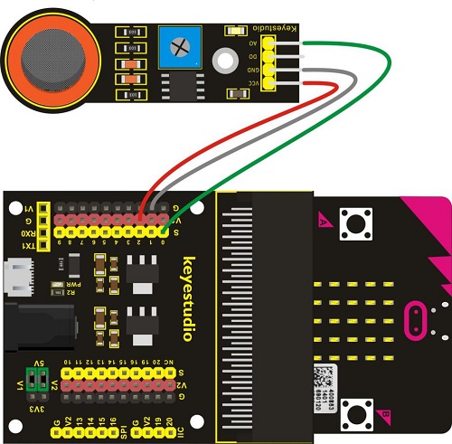
3. Connection Diagram
4. Test Code
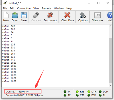
5. Test Results
Wire components up, plug in external power and transfer code to the micro:bit. The higher the concentration of alcohol, the larger the data. The data can be shown on the micro:bit and monitor.
Open CoolTerm, click Options and select SerialPort, set COM port and baud rate(115200). Click OK and Connect.
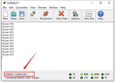
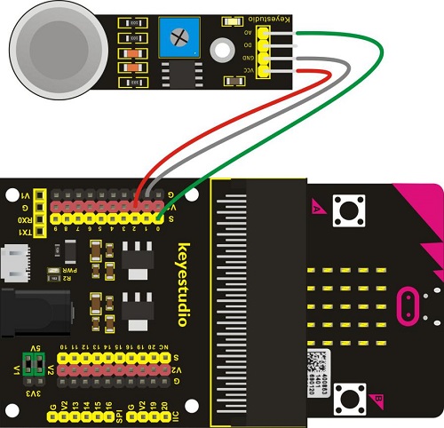
Project 37: Flammable Gas in the Air
1. Project Introduction:
In real life, gas leakage events often occur. If toxic or flammable and explosive gas are leaked out, there exist huge potential hazards to people’s health. So people have developed different kinds of sensors to detect various gas contents in the air, which can timely alarm to process the leaking gas.
In this project, you will learn how to use an analog gas sensor and micro:bit to detect the flammable gas in the air. Show the analog value of gas on the LED matrix of micro:bit or check it on the serial monitor.
2. Components Needed:
Micro:bit main board*1
Keyestudio Micro bit Sensor V2 Shield*1
USB Cable*1
keyestudio MQ-2 Gas Sensor*1
DuPont jumper wires
3. Connection Diagram
4. Test Code
5. Test Results
Wire components up, plug in power and upload code to micro:bit. The stronger the combustible gas is, the larger the data displays. You can view the data on the micro:bit and CoolTerm monitor. Open CoolTerm, click Options and select SerialPort, set COM port and baud rate(115200). Click OK and Connect.
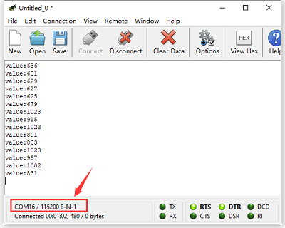
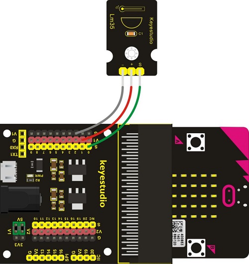
Project 38: Ambient Temperature Detection
1. Project Introduction:
In the previous project 23, we only get the analog value of temperature in the current environment. Now, we are going to use a LM35 linear temperature sensor to detect the ambient temperature. Finally get the specific temperature value of current ambient via calculating, and display it on the micro:bit LED matrix or on the CoolTerm monitor.
2. Components Needed:
Micro:bit main board*1
Keyestudio Micro bit Sensor V2 Shield*1
USB Cable*1
keyestudio LM35 Linear Temperature Sensor*1
DuPont jumper wires
3. Connection Diagram
4. Test Code
5. Test Results
Wire up components, plug in power and transfer code to the micro:bit. Open CoolTerm, click Options and select SerialPort, set COM port and baud rate(115200). Click OK and Connect. Then the CoolTerm monitor and the micro:bit display the current temperature, as shown below:
Project 39: TEMT6000 Sensor
1. Project Introduction:
This lesson is a little bit similar to the previous illumination test by a photocell. But this time we will use keystudio TEMT6000 light sensor whose sensitivity is better than a photocell.
You will learn how to use a TEMT6000 sensor and micro:bit to test the ambient light. Show the analog value on the micro:bit LED matrix or on the CoolTerm monitor.
2. Components Needed:
Micro:bit main board*1
Keyestudio Micro bit Sensor V2 Shield*1
USB Cable*1
TEMT6000 Ambient Light Sensor*1
DuPont jumper wire*3
3. Connection Diagram

4. Test Code
5. Test Results
Wire up components, plug in power and transfer code to the micro:bit. Open CoolTerm, click Options and select SerialPort, set COM port and baud rate(115200). Click OK and Connect.
Then the CoolTerm monitor and the micro:bit display the light intensity value, as shown below:
Project 40: Automatically Watering Device
1. Project Introduction:
In life, you may often water some flowers and plants from time to time to prevent them from withering, but not need to pour more. It may requires experience. So can we make a system that allows the machine to automatically water the plants’ soil when it is dry? Of course yes.
In this project, you will learn how to use a soil sensor and micro:bit to detect the humidity of your plants’ soil. Display the analog value on the micro:bit LED matrix or on the serial monitor. The greater the humidity, the greater the analog value.
2. Components Needed:
Micro:bit Main board*1
Keyestudio Micro bit Sensor V2 Shield*1
USB Cable*1
keyestudio Soil Humidity Sensor*1
DuPont jumper wires
3. Connection Diagram
4. Test Code
5. Test Results
Wire up according to connection diagram. Plug in external power and upload code to micro:bit, open CoolTerm, click Options and select SerialPort, set COM port and baud rate(115200). Click OK and Connect.
Insert soil humidity sensor into soil. The humidity value varies with the humidity. The higher the humidity is, the larger the humidity value is.
Project 41: Water Level Alarm
1. Project Introduction:
In real life, when heavy rain occurs, the water level in a river or a reservoir will rise sharply. When reaching a certain water level, it is necessary to open a floodgate to solve the safety hazard. However, how to detect the water level in a river or a reservoir? Very simple, use a water level sensor.
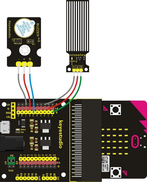
In this experiment, we are about to use a water sensor and a buzzer module to detect the water level in the glass, if beyond level, buzzer should make an alarm.
2. Components Needed:
Micro:bit main board*1
Keyestudio V2 Shield*1
USB Cable*1
Keyestudio Water level Sensor*1
Keyestudio Digital Buzzer Module*1
DuPont jumper wires
3. Connection Diagram
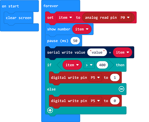
4. Test Code
5. Test Results
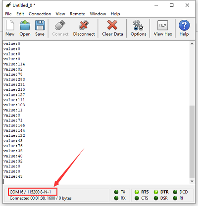
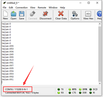
Wire components up, plug in external power and transfer code to micro:bit. Open CoolTerm, click Options and select SerialPort, set COM port and baud rate(115200). Click OK and Connect. The micro:bit and CoolTerm software show the analog value. The stronger the UV radiation, the larger the number is.
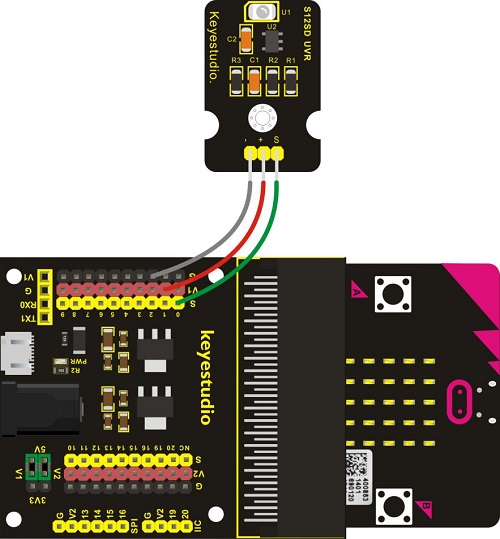
Project 42: Ultraviolet Detection
1. Project Introduction:
In this project, you will learn how to use Ultraviolet sensor and micro:bit to detect the ultraviolet light. Show the analog value on the micro:bit LED matrix or on the CoolTerm monitor.
This sensor mainly includes GUVA-S12SD, applied to measure ultraviolet index of intelligent wearable device, such as watches, smart phone and outdoor device with UV index.
In the aspect of disinfection by ultraviolet rays, it can be used to monitor the intensity of ultraviolet light or used as a UV flame detector.
2. Components Needed:
Micro:bit main board*1
Keyestudio Micro bit Sensor V2 Shield*1
USB Cable*1
Keyestudio GUVA-S12SD 3528 Ultraviolet Sensor*1
DuPont jumper wires
3. Connection Diagram
4. Test Code
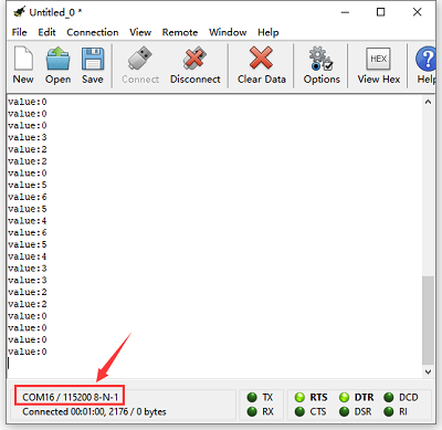
5. Test Results
Wire up components,plug in external power and upload code to micro:bit,open CoolTerm, click Options and select SerialPort, set COM port and baud rate(115200). Click OK and Connect. The CoolTerm serial monitor shows the analog signal read by ultraviolet sensor. The greater the Ultraviolet light, the greater the value.
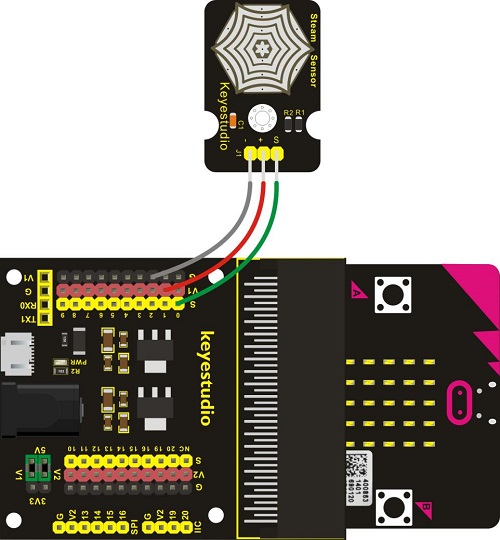
Project 43: Vapor in the Air
1. Project Introduction:
Our lives are surrounded by air everywhere. The air contains many ingredients, some of which are useful, some are harmful, some of which have a significant impact on the human body, and some of which have a slight effect on the human body.
So in this lesson, you will learn how to use a steam sensor and micro:bit to detect the vapor content in the air. Show the analog value on the micro:bit LED matrix or on the serial monitor.
2. Components Needed:
Micro:bit main board*1
Keyestudio Micro bit Sensor V2 Shield*1
USB Cable*1
keyestudio Steam Sensor*1
DuPont jumper wires
3. Connection Diagram
4. Test Code
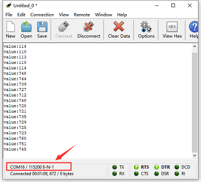
5. Test Results
Wire up components,plug in power and upload code to the micro:bit,Open CoolTerm, click Options and select SerialPort, set COM port and baud rate(115200). Click OK and Connect. The CoolTerm serial monitor shows the analog signal read by steam sensor. The higher the vapor content is in the air, the greater the value is. The micro:bit and monitor show the value.
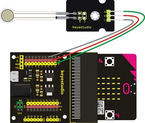
Project 44: Pressure Detection
1. Project Introduction:
In the previous projects, you have learned various external information detected by different sensors, such as temperature, light, sound, gas, and so on. Now, let’s use the Keyestudio thin-film pressure sensor and micro:bit to detect external stress. Show the analog value of pressure on the micro:bit LED matrix or on the serial monitor.
2. Components Needed:
Micro:bit main board*1
Keyestudio Micro bit Sensor V2 Shield*1
USB Cable*1
keyestudio Thin-film Pressure Sensor*1
Dupont jumper wires
3. Connection Diagram
4. Test Code
5. Test Results
Wire up components, plug in power and upload code to the micro:bit,open CoolTerm, click Options and select SerialPort, set COM port and baud rate(115200). Click OK and Connect. The stronger the pressure is on the thin film, the larger the analog value is, as shown on CoolTerm monitor:
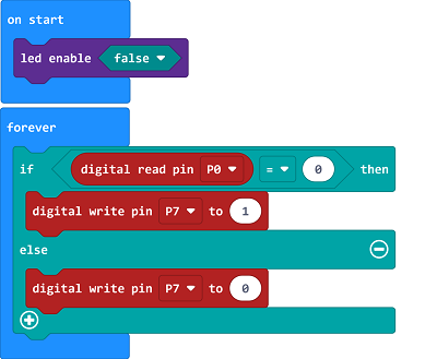
Project 45:Light Controlled by Vibration
1. Project Introduction:
In this project, you will learn how to use a vibration sensor and micro:bit to control an LED on and off.
This sensor is mainly based on a 801S sensor element. The interior structure is a metal ball fixed on a special spring as a pole, and the other surrounded by it as another pole. Once the vibration reaches a certain amplitude, the two poles are connected.
2. Components Needed:
Micro:bit main board*1
Keyestudio Micro bit Sensor V2 Shield*1
USB Cable
Keyestudio Vibration Sensor
keyestudio Piranha While LED Module
Dupont jumper wires
3. Connection Diagram
4. Test Code
5. Test Results
Hook up the components, upload code and plug in power. When the vibration signals are detected by the vibration sensor, the white LED is on.
Project 46: Joystick
1. Project Introduction:
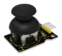
For some DIY projects, you perhaps use a component, that is, joystick module, such as game joysticks. How could they operate?
In this lesson, you will learn how to control a joystick module and micro:bit shield to display the data on serial monitor.
Lots of interactive projects may need joystick. This module provides an affordable solution, easy to use.
On the joystick module, it has 3 signal interfaces, which can simulate the three-dimensional space. The signal pins X and Y will simulate the X-and Y-axis of space. Connect them to Analog Input of microcontroller. By controlling 2 analog input values to control the coordinate of an object in X- or Y-axis.
Another signal pin Z( labeled B on the module) will simulate the Z-axis of space. Generally connected to Digital port, and used as a button.
2. Components Needed:
Micro:bit main board*1
Keyestudio Micro bit Sensor V2 Shield*1
USB Cable*1
keyestudio Joystick Module*1
DuPont jumper wires
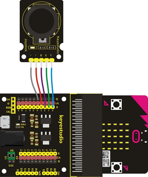
3. Connection Diagram
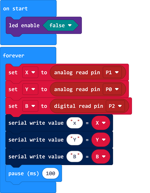
4. Test Code
5. Test Results
Wire up according to connection diagram. plug in external power and upload code to micro:bit. Open CoolTerm, click Options and select SerialPort, set COM port and baud rate(115200). Click OK and Connect.
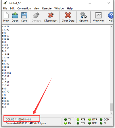
If you operate the joystick, the analog value on X, Y and B will change, as well as pin B, as shown below:
Project 47: Micro Servo
1. Project Introduction:
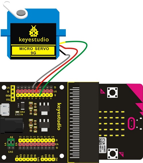
For those DIY smart cars, they often have a function of automatic obstacle avoidance. In the DIY process, we need a servo to control the ultrasonic module to rotate left and right, and then to detect the distance between car and obstacles, so as to control the car to avoid obstacles.
If use other microcontrollers to control the rotation of servo, we need to set a pulse of a certain frequency and a certain width in order to control the servo angle.
But if use the micro bit main board to control the servo angle, we only need to set the control angle in the development environment. The corresponding pulse will be automatically set in the development environment to control the servo rotation.
In this project, you will learn how to control the micro servo rotate back and forth between 0°and 90°.
2. Components Needed:
Micro:bit main board*1
Keyestudio Micro bit Sensor V2 Shield*1
USB Cable*1
keyestudio Micro Servo*1
3. Connection Diagram
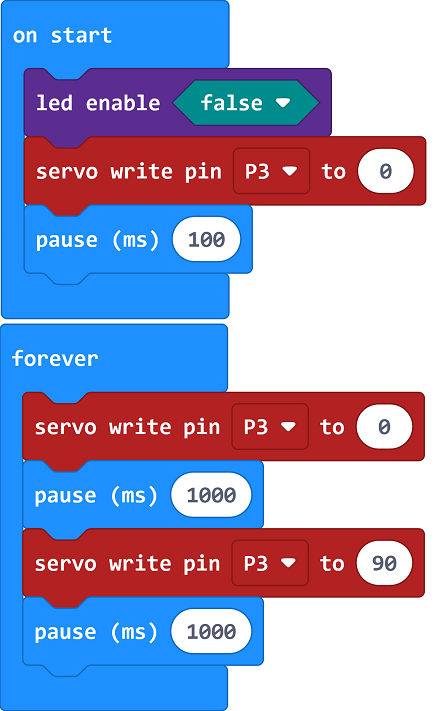
4. Test Code
5. Test Results
Done wiring and plug in external power,send the above code to micro:bit. You should see the servo turn back and forth between 0° and 90°.
Project 48: Add An LCD
1. Project Introduction:
In life, we can use the display and other sensors to do a variety of experiments. You can DIY a variety of small items. For example, use a temperature module and display to make a temperature tester, or use an ultrasound module and display to make a distance tester.
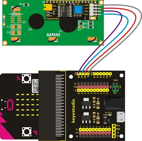
In the following, we will use keyestudio 1602 I2C module as the display, connect it to I2C pin headers of micro:bit shield. You will learn how to control the 1602 LCD show the character“keyestudio”and number.
2. Components Needed:
Micro:bit main board*1
Keyestudio Micro bit Sensor V2 Shield*1
USB Cable*1
keyestudio 1602 I2C Module*1
DuPont jumper wires
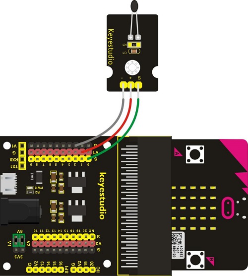
3. Connection Diagram
4. Test Code
Set code with the library. Copy and search the following extension library lcd1602 in the extension:
https://github.com/xuefengedu/pxt-lcd1602_CN
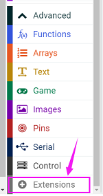
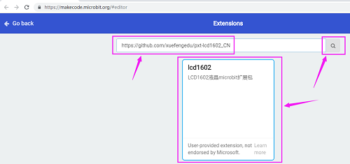
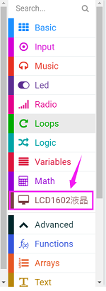
Then you can view it in the listed blocks.
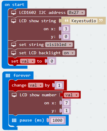
5. Test Results
Note: You can adjust the potentiometer at the back to make the displayed characters brighter if the screen doesn’t show characters. Wire up the components, upload code and plug in power, then 1602LCD will show “keyestudio” on the first line, and numbers on the second line.
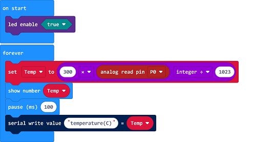
Project 49: Analog Temperature
1. Project Introduction:
In this project, we are going to detect another important index in the environment, that is, temperature. You will learn how to use an analog temperature sensor and micro:bit to display the analog value of current temperature on the micro:bit LED matrix or on the CoolTerm monitor.
This analog temperature module is based on a thermistor whose resistance varies with temperature change.
It can detect surrounding temperature changes in real time.
Through the circuit connection, convert the resistance changes into voltage changes, then input the voltage changes into Analog Input of micro:bit via signal end. Actually the analog value of micro:bit can be calculated into temperature value via programming.
This sensor is convenient and effective, widely applied to home alarm system, gardening, and other devices.
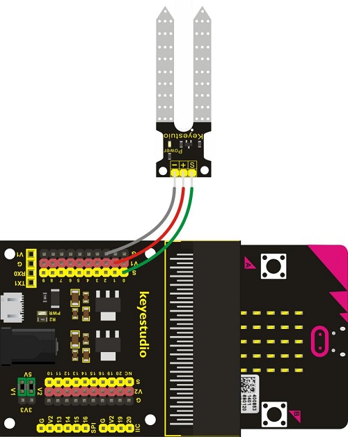
2. Components Needed:
Micro:bit main board*1
Keyestudio Micro bit Sensor V2 Shield*1
USB Cable*1
keyestudio Analog Temperature Sensor*1
DuPont jumper wires
3. Connection Diagram
4. Test Code
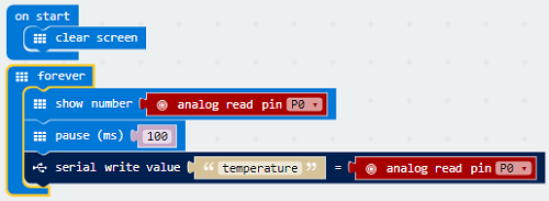
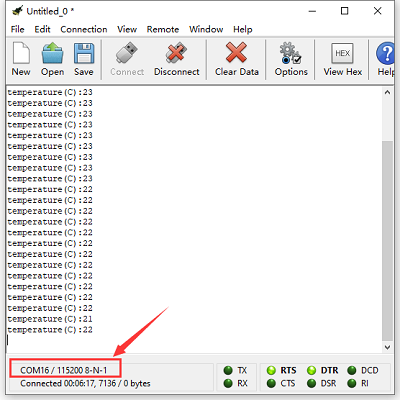
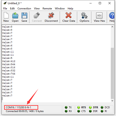
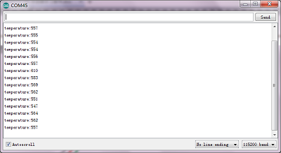
5. Test Results
Hook up components, upload code and plug in power. You can check the data on the micro:bit and monitor.
6. Resources:
https://fs.keyestudio.com/KS0361-0365
https://makecode.microbit.org/
https://tech.microbit.org/hardware/
https://microbit.org/new-microbit/
https://www.microbit.org/get-started/user-guide/overview/
https://microbit.org/get-started/user-guide/features-in-depth/
https://tech.microbit.org/hardware/edgeconnector/
https://microbit.org/guide/hardware/pins/
https://microbit.org/guide/quick/